
Choosing the right satellite converter architecture can feel complex. A wrong decision can lead to poor performance, but understanding the core trade-offs makes the choice clear and simple.
For high-performance Ka/Ku band satellite communication, a double-conversion architecture is almost always the best choice1. It effectively eliminates image frequency problems without sacrificing the system's noise figure2, resulting in a cleaner signal and superior reliability compared to a simpler single-stage design.
I remember asking my mentor this exact question early in my career. The answer wasn't just about cost. It was a deep lesson in the physics of frequency mixing and system performance. The more complex solution is often the right one for a reason, especially in demanding applications like satellite links. Let's explore why this is the case and how we ensure our designs are flawless from the start.
Why Does Single-Stage Conversion Cause Performance Headaches?
You want a simple, cost-effective design. But single-stage converters, while cheaper upfront, often create stubborn image frequency issues3 that compromise the integrity of your entire communication link.
A single-stage converter places the image frequency extremely close to your desired signal. Filtering this unwanted signal requires sharp, expensive filters. These filters can degrade your system's noise figure (NF), harming the very signal quality you need to protect.

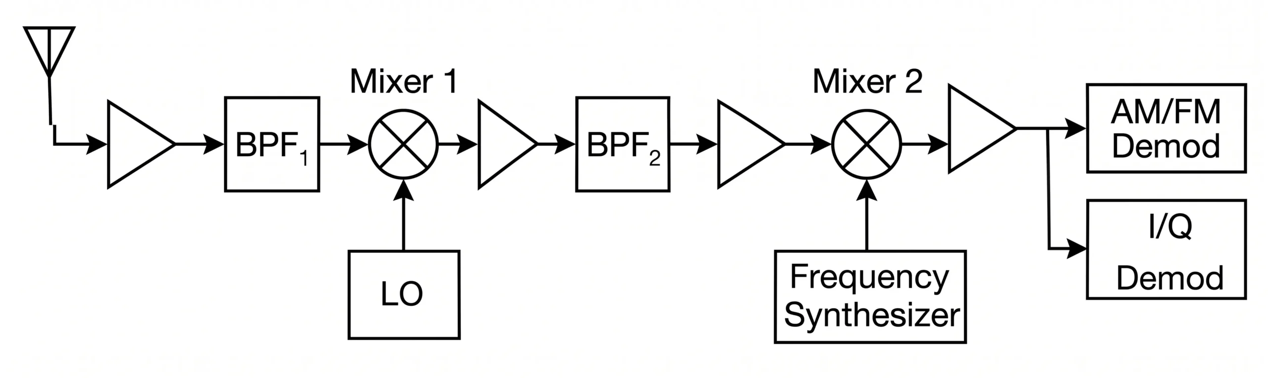
In a single-stage downconverter, the mixer combines the incoming high-frequency RF signal with a Local Oscillator (LO) signal to produce a lower Intermediate Frequency (IF). The problem is that another frequency, the "image," also mixes with the LO to produce the same IF. This image is separated from your wanted RF signal by only twice the IF (2 x f_IF)4. For Ka/Ku band systems converting down to a standard L-band IF (e.g., 950-2150 MHz)5, this separation is very small. To remove the image, you need a filter right at the input, before the Low Noise Amplifier (LNA). A filter sharp enough to do the job will have significant insertion loss, and any loss before the first LNA adds directly, decibel for decibel, to your system's total noise figure6. This completely undermines the performance of a sensitive receiver.
| パラメータ | Single-Stage Conversion | Consequence |
|---|---|---|
| Image Frequency | Close to RF signal (separated by 2 x IF) | Requires sharp, high-loss filters. |
| Filtering | Difficult and often compromises performance. | High filter insertion loss directly increases the system Noise Figure (NF). |
| ノイズ指数 | Degraded by the need for a sharp pre-LNA filter. | Reduced signal-to-noise ratio (SNR) and overall link quality. |
| Cost | Lower initial component cost. | Higher engineering and troubleshooting costs to deal with performance issues. |
How Does Double-Conversion Solve the Image Problem?
You need a clean, reliable signal free from interference. Image frequencies and other unwanted signals are a constant threat. A double-conversion architecture provides a robust, multi-step solution to eliminate them.
This architecture uses two stages. The first stage converts the signal to a high Intermediate Frequency (IF), which pushes the image frequency far away. A simple, low-loss filter can then easily remove it, preserving the system's excellent noise figure.

Let’s walk through the process. A Ka-band signal at 20 GHz enters the first mixer. We mix it with a 15 GHz LO to create a high first IF of 5 GHz. The image frequency is now at 10 GHz (15 GHz LO - 5 GHz IF). The separation between our wanted 20 GHz signal and the 10 GHz image is a massive 10 GHz. This wide gap allows us to use a simple and very effective low-loss filter, like a Surface Acoustic Wave (SAW) filter, to achieve over 50 dB of image rejection7 without impacting the noise figure. Once the signal is "cleaned" at this high IF, a second mixer down-converts the 5 GHz signal to the final L-band IF. A potential concern is the added phase noise from two LOs. We solve this by cURL Too many subrequests by single Worker invocation. To configure this limit, refer to https://developers.cloudflare.com/workers/wrangler/configuration/#limits8. cURL Too many subrequests by single Worker invocation. To configure this limit, refer to https://developers.cloudflare.com/workers/wrangler/configuration/#limits.
| パラメータ | cURL Too many subrequests by single Worker invocation. To configure this limit, refer to https://developers.cloudflare.com/workers/wrangler/configuration/#limits | cURL Too many subrequests by single Worker invocation. To configure this limit, refer to https://developers.cloudflare.com/workers/wrangler/configuration/#limits |
|---|---|---|
| cURL Too many subrequests by single Worker invocation. To configure this limit, refer to https://developers.cloudflare.com/workers/wrangler/configuration/#limits | cURL Too many subrequests by single Worker invocation. To configure this limit, refer to https://developers.cloudflare.com/workers/wrangler/configuration/#limits | cURL Too many subrequests by single Worker invocation. To configure this limit, refer to https://developers.cloudflare.com/workers/wrangler/configuration/#limits. |
| cURL Too many subrequests by single Worker invocation. To configure this limit, refer to https://developers.cloudflare.com/workers/wrangler/configuration/#limits | cURL Too many subrequests by single Worker invocation. To configure this limit, refer to https://developers.cloudflare.com/workers/wrangler/configuration/#limits. | cURL Too many subrequests by single Worker invocation. To configure this limit, refer to https://developers.cloudflare.com/workers/wrangler/configuration/#limits. |
| 位相ノイズ | cURL Too many subrequests by single Worker invocation. To configure this limit, refer to https://developers.cloudflare.com/workers/wrangler/configuration/#limits. | cURL Too many subrequests by single Worker invocation. To configure this limit, refer to https://developers.cloudflare.com/workers/wrangler/configuration/#limits. |
| Complexity | cURL Too many subrequests by single Worker invocation. To configure this limit, refer to https://developers.cloudflare.com/workers/wrangler/configuration/#limits. | cURL Too many subrequests by single Worker invocation. To configure this limit, refer to https://developers.cloudflare.com/workers/wrangler/configuration/#limits. |
How Can We Perfect the Design with Software Simulation?
cURL Too many subrequests by single Worker invocation. To configure this limit, refer to https://developers.cloudflare.com/workers/wrangler/configuration/#limits.
cURL Too many subrequests by single Worker invocation. To configure this limit, refer to https://developers.cloudflare.com/workers/wrangler/configuration/#limits cURL Too many subrequests by single Worker invocation. To configure this limit, refer to https://developers.cloudflare.com/workers/wrangler/configuration/#limits"9 cURL Too many subrequests by single Worker invocation. To configure this limit, refer to https://developers.cloudflare.com/workers/wrangler/configuration/#limits.
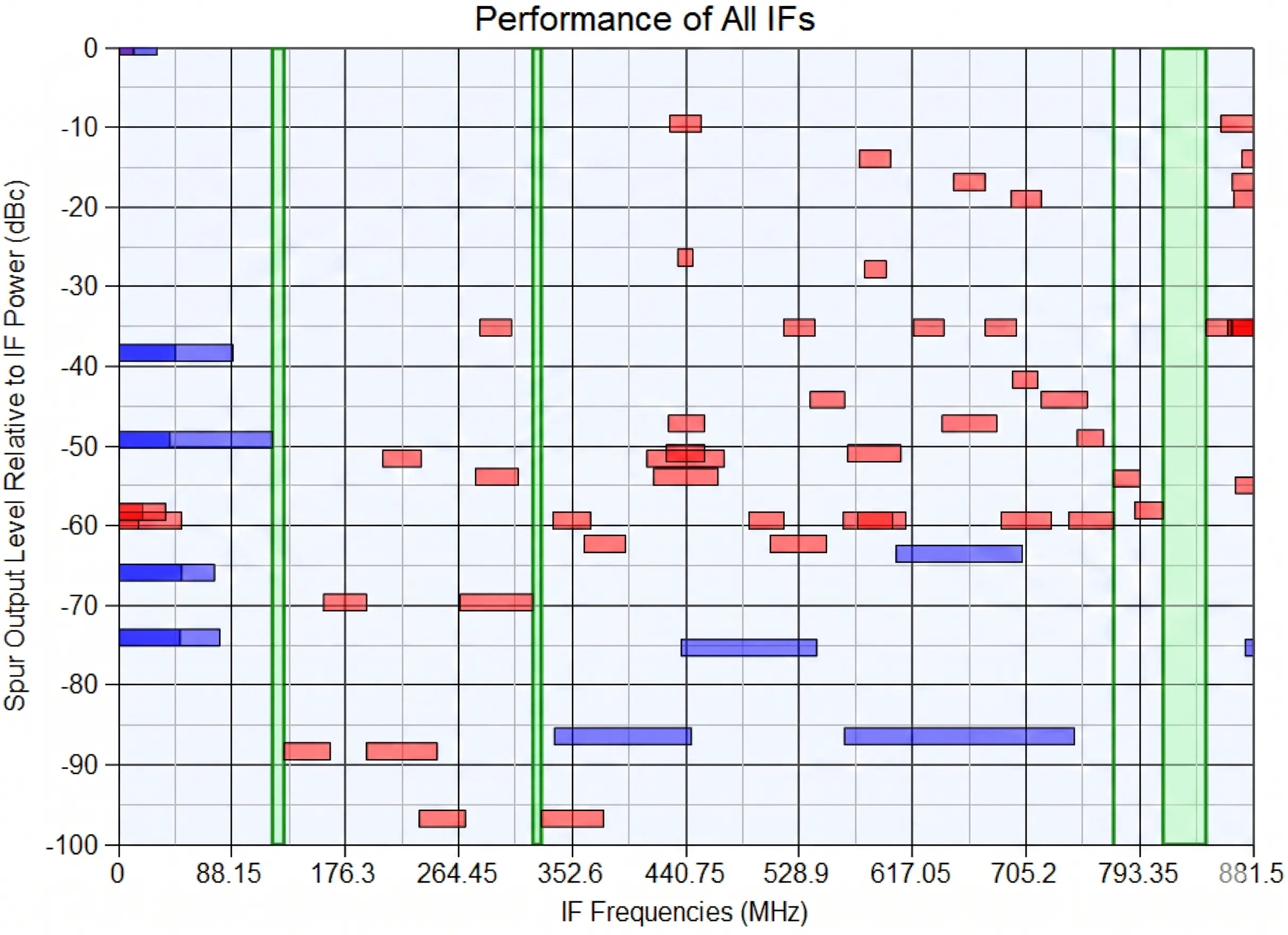
cURL Too many subrequests by single Worker invocation. To configure this limit, refer to https://developers.cloudflare.com/workers/wrangler/configuration/#limits mcURL Too many subrequests by single Worker invocation. To configure this limit, refer to https://developers.cloudflare.com/workers/wrangler/configuration/#limitscURL Too many subrequests by single Worker invocation. To configure this limit, refer to https://developers.cloudflare.com/workers/wrangler/configuration/#limits10. cURL Too many subrequests by single Worker invocation. To configure this limit, refer to https://developers.cloudflare.com/workers/wrangler/configuration/#limits. cURL Too many subrequests by single Worker invocation. To configure this limit, refer to https://developers.cloudflare.com/workers/wrangler/configuration/#limits.11 This predictive analysis saves us countless hours of debugging and ensures our products, from our 110 GHz amplifiers to our complex switch matrices, perform flawlessly.
結論
For high-performance Ka/Ku band systems, double-conversion is the superior choice. It offers unmatched image rejection and signal purity, which is why we build our advanced converters this way.
"Comparison of Double and Single Conversion Receivers for Radio ...", https://www.facebook.com/groups/532613604253401/posts/1800988987415850/. Provides an overview of receiver architectures, noting that the superheterodyne (double-conversion) design is widely used in demanding applications like satellite communications to effectively manage image frequencies and improve selectivity. Evidence role: general_support; source type: paper. Supports: That double-conversion (superheterodyne) architectures are often preferred for high-performance satellite systems due to superior image rejection.. ↩
"Superheterodyne receivers | RF Design Guide", https://www.cdt21.com/design_guide/superheterodyne-receivers/. Explains that in a double-conversion receiver, the first, high intermediate frequency places the image frequency far from the desired signal, allowing for filtering with low insertion loss, which is critical for maintaining a low overall system noise figure. Evidence role: mechanism; source type: education. Supports: That using a high first IF in a double-conversion architecture allows for effective image filtering with low-loss filters, thereby preserving the receiver's low noise figure.. ↩
"Direct-conversion receiver - Wikipedia", https://en.wikipedia.org/wiki/Direct-conversion_receiver. Discusses the design trade-offs of receiver architectures, noting that single-stage converters can suffer from poor image rejection, which requires sharp, and potentially high-loss, pre-selection filters. Evidence role: general_support; source type: paper. Supports: That single-stage converters face significant challenges with image frequency rejection, especially when the IF is low relative to the RF.. ↩
"Image-Frequency Interferences - Radartutorial.eu", https://www.radartutorial.eu/09.receivers/rx06.en.html. Defines the image frequency (f_image) in a superheterodyne receiver and shows that for a given RF signal (f_RF), the image is separated by a frequency of 2 × f_IF when using low-side local oscillator injection. Evidence role: definition; source type: encyclopedia. Supports: The mathematical relationship between the RF, LO, and image frequencies in a mixer.. Scope note: The exact formula for the image frequency's location depends on whether high-side or low-side injection is used, but the separation of 2 × f_IF from the desired signal is a standard result. ↩
"L band", https://en.wikipedia.org/wiki/L_band. Describes the standard frequency bands used in satellite television reception, specifying the L-band range of 950 MHz to 2150 MHz as the standard Intermediate Frequency (IF) for signals delivered from the LNB to the indoor satellite receiver. Evidence role: general_support; source type: institution. Supports: That the 950-2150 MHz frequency range is a commonly used standard for the L-band Intermediate Frequency (IF) in satellite communication systems.. ↩
"Friis formulas for noise - Wikipedia", https://en.wikipedia.org/wiki/Friis_formulas_for_noise. Explains the Friis formula for noise figure in a cascade of components, demonstrating that the loss (in dB) of any passive component (like a filter) placed before the first active amplifier adds directly to the total system noise figure (in dB). Evidence role: mechanism; source type: education. Supports: That the noise figure of a cascaded system is dominated by the noise figure of the first stage and any loss preceding it.. ↩
"What is Saw Filter? Exploring Theory, Applications, and Design", https://www.temwell.com/en/pages/what-is-saw-filter. Provides data on the performance of Surface Acoustic Wave (SAW) filters, showing they can offer sharp filter skirts and high out-of-band rejection, often exceeding 50 dB, making them suitable for IF filtering applications where high selectivity is required. Evidence role: general_support; source type: paper. Supports: That SAW filters are capable of providing high rejection levels suitable for IF filtering.. Scope note: The exact rejection level depends on the specific filter design and frequency of operation. ↩
"Phase-locked loop - Wikipedia", https://en.wikipedia.org/wiki/Phase-locked_loop. Explains the principle of using a common reference oscillator to discipline multiple Phase-Locked Oscillators (PLOs), noting that this technique transfers the stability and low phase noise characteristics of the reference to the output signals of the PLOs. Evidence role: mechanism; source type: paper. Supports: That locking multiple Phase-Locked Oscillators to a single high-stability reference source ensures frequency coherence and minimizes phase noise contributions.. ↩
"[PDF] Frequency Planning Fundamentals", https://docs.keysight.com/spaces/flyingpdf/pdfpageexport.action?pageId=7528986. Defines a spurious frequency plan (or spur analysis) as a critical step in RF system design where all potential unwanted frequencies (spurs) generated by mixers are calculated and mapped to ensure they do not fall within desired signal bands. Evidence role: definition; source type: education. Supports: The definition and purpose of a spurious frequency plan or spur analysis in RF system design.. ↩
"Intermodulation - Wikipedia", https://en.wikipedia.org/wiki/Intermodulation. Provides the mathematical formula for calculating the frequencies of intermodulation distortion products (spurs) generated in a mixer as f_spur = m*f_LO ± n*f_RF, where m and n are integers representing the harmonic numbers of the local oscillator and radio frequency signals, respectively. Evidence role: definition; source type: encyclopedia. Supports: The general formula used to predict the frequencies of intermodulation products generated by a mixer.. ↩
"Discovering Advanced Design System (ADS) - Keysight", https://www.keysight.com/us/en/lib/resources/demos/discovering-advanced-design-system-ads-1729588.html. Provides an application note or tutorial demonstrating the use of RF simulation software to generate a spur chart and iteratively adjust system parameters like LO and IF frequencies to mitigate interference from spurious products. Evidence role: case_reference; source type: other. Supports: That RF simulation software is used to visualize spurious products and allows designers to optimize frequency plans by adjusting LO and IF frequencies.. Scope note: The source may be from a software vendor but can be used to support the described methodology rather than to promote a specific product. ↩
