
Your downconversion system is live, but the spectrum is a mess of spurs and IMD. This ruins performance. I'll show you a fast, step-by-step method to fix it.
Start by disconnecting the RF input. If spurs vanish, check the LNA or add an attenuator. If they persist, inspect the LO and power supply for ripple. If all else fails, the problem is likely LO signal crosstalk, which can be verified with absorbing material.
Finding the root cause of these unwanted signals can feel like searching for a needle in a haystack. But with a logical process, you can systematically eliminate possibilities and pinpoint the exact problem. Let's break down the first step, which is often the most revealing.
Is Your LNA Overloading the Mixer?
You suspect the front-end is the problem, but how can you be sure? A saturated mixer creates a cascade of issues.1 Here's a simple test to confirm it.
Disconnect the RF input from your mixer. If the spurs and IMD disappear from the spectrum analyzer, the issue originates before the mixer. The LNA is either generating noise or its output power is too high, causing saturation. Add an external attenuator to verify.
In my experience as a Field Application Engineer (FAE), the front-end is the first place to look. When a mixer receives too much power, it stops behaving linearly2. This is called saturation or compression. Instead of just mixing your RF and LO signals cleanly, it starts generating a host of unwanted new signals. These are the intermodulation distortion (IMD) products3 and spurs that clutter your spectrum and degrade your system's performance. A common cause is the Low Noise Amplifier (LNA) placed right before the mixer. The LNA's job is to boost weak signals, but it can easily overload the mixer if its gain is too high or the input signal is stronger than expected.
A Simple Diagnostic Test
The first thing I always do is disconnect the RF cable from the mixer's input port and terminate it properly. Then, I look at the spectrum analyzer displaying the mixer's output. If the spurs and IMD are gone, the problem is coming from your upstream components. To confirm this, I reconnect everything but add a fixed attenuator, like 3 dB or 6 dB, between the LNA and the mixer. This reduces the power level. If the IMD products decrease by much more than the attenuation value4, you've proven the mixer was being driven into compression.
Understanding the Impact
This test helps you quickly isolate the problem to the front-end of your system. Here’s a quick reference table for this process.
| Step | Action | Expected Result if LNA is Overloading Mixer |
|---|---|---|
| 1 | Disconnect RF input from mixer. | Unwanted spurs and IMD products disappear. |
| 2 | Reconnect with an attenuator before the mixer. | IMD products decrease significantly. |
Once you confirm this, the solution is to either reduce the LNA gain or choose a mixer with a higher 1dB compression point (P1dB) and a better third-order intercept point (IP3)5 to handle the power.
Could Your Power Supply or LO Be the Source of Spurs?
You've ruled out the input stage, but the spurs remain. This points to internal issues. The power supply or the Local Oscillator might be injecting noise directly into your system.
If spurs persist after disconnecting the RF input, the cause is likely the Local Oscillator (LO) or the power supply. Use a signal analyzer to measure the power supply ripple. Check if the ripple's frequency matches the frequency difference between your carrier and the unwanted spur.
If the spurs are still there with the RF input disconnected, the problem is being generated within or around the mixer itself. The two most common culprits are the power supply and the Local Oscillator (LO). Active components like mixers need perfectly clean DC power to operate correctly. Any noise or ripple on the power supply lines can act like a tiny signal, modulating the LO signal inside the mixer. This creates unwanted sidebands, which we see as spurs on the spectrum analyzer. I often see this with switching power supplies. They are very efficient but can introduce noise if not designed with adequate filtering6 for sensitive RF applications.
How to Find the Noise Source
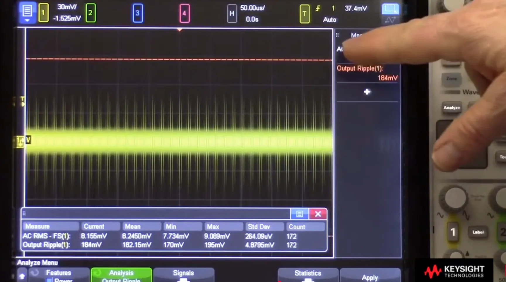
The test for this is straightforward. Use a signal analyzer or a good oscilloscope with an FFT function to look at the DC voltage rail that powers the mixer. For example, let's say your Intermediate Frequency (IF) is at 140 MHz and you see a strange spur at 140.05 MHz. The frequency difference between your desired signal and the spur is 50 kHz. If you then measure the DC power line and discover a significant 50 kHz ripple, you have found your problem. The power supply noise is mixing with your LO and showing up at the IF.
Don't Forget the LO
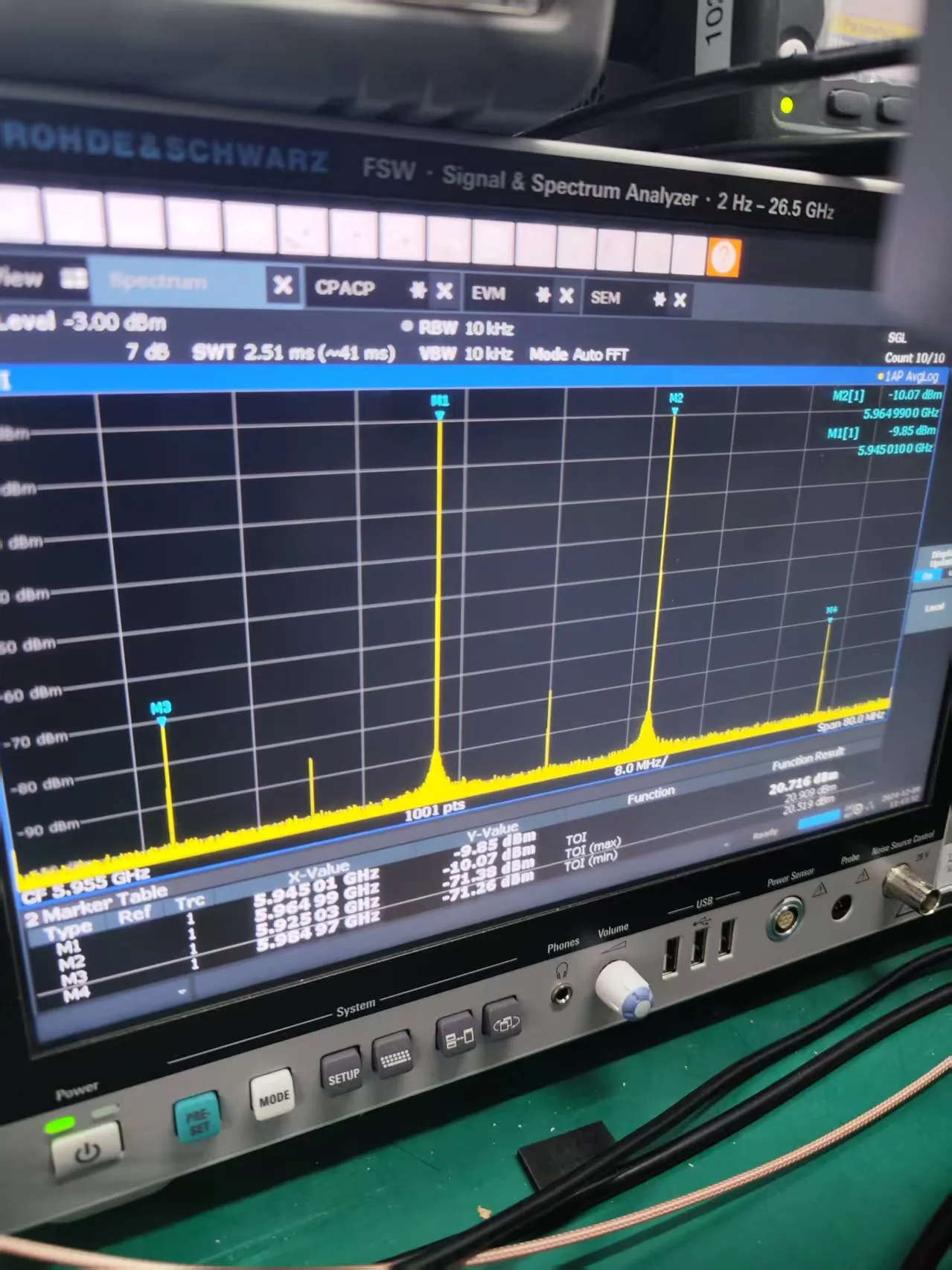
The LO itself can also be the source. A poor-quality LO signal may have its own spurs or high phase noise7. These imperfections will mix with the RF signal and get passed directly to your IF output, creating unwanted signals that are impossible to filter out later. Always use a spectrum analyzer to verify the purity of your LO source before connecting it to the mixer.
| Signal Frequency (IF) | Spur Frequency | Frequency Difference | Potential Cause |
|---|---|---|---|
| 140 MHz | 140.05 MHz | 50 kHz | 50 kHz ripple on a DC power line. |
| 70 MHz | 69.9 MHz | 100 kHz | 100 kHz ripple from a switching supply. |
A well-regulated, low-noise power supply using Low-Dropout Regulators (LDOs)8 is critical for any serious RF system.
What If the Problem Is Invisible Signal Crosstalk?
You have checked the inputs and the power lines, but the spurs just will not go away. The problem might be invisible to your probes: signals leaking where they should not. This is crosstalk.
If all other tests fail, suspect signal crosstalk. The high-power LO signal is a common offender, leaking into other parts of the circuit. Proper grounding and shielded cavities in the design are critical for isolation. A temporary fix can confirm this diagnosis.

When you have exhausted the other possibilities, the most likely remaining cause is crosstalk. Crosstalk happens when a signal from one part of a circuit couples into another part9 where it is not wanted. In downconversion systems, the LO is almost always the main suspect. The LO signal is typically very strong, often +10 dBm or higher, while the incoming RF signal can be very weak. If the circuit board layout or module housing is not designed carefully, this powerful LO signal can radiate or conduct into the sensitive RF or IF pathways. It then mixes with itself or other signals, creating a confusing mess of spurs that seem to come from nowhere.
The Right Way vs. A Quick Test
The permanent solution to crosstalk is good engineering design from the beginning. This means a carefully planned PCB layout with solid ground planes, physical separation between high-power and low-power sections, and using metal shields or individual cavities to isolate components. At Safari Microwave, our 30 years of engineering experience are focused on designing high-isolation components, like our power dividers and RF switches, to prevent these issues internally. For instance, our SP8T switches and 128-way power dividers are designed with excellent isolation to ensure signal integrity.
But how do you prove crosstalk is the problem in a system that is already built? Here is a simple trick I use on customer sites. I take a small piece of microwave absorbing material10 and gently press it onto the metal lid or housing directly over the LO circuitry. This flexible, lossy material disrupts the electromagnetic fields and can break up a resonant condition that might be amplifying the leakage. If you see the troublesome spurs drop in amplitude on your spectrum analyzer, you have confirmed that LO crosstalk is your problem. This tells you that you need to improve the shielding or grounding in that area.
Conclusion
Systematically checking the input, power supply, and for crosstalk will help you quickly find and fix spur and IMD issues in your downconversion system.
"Frequency mixer - Wikipedia", https://en.wikipedia.org/wiki/Frequency_mixer. A source can explain the concept of mixer saturation, or compression, where excessive input power causes the device to operate in a non-linear region, resulting in the creation of unwanted spectral components like harmonics and intermodulation products. Evidence role: mechanism; source type: education. Supports: The source should explain that when a mixer is saturated (driven into compression), its output is no longer a linear function of its input, leading to the generation of harmonic and intermodulation distortion products.. ↩
"[PDF] Mixer Compression and Intercept Points", http://www.ittc.ku.edu/~jstiles/622/handouts/Mixer%20Compression%20and%20Intercept%20Points.pdf. A source can define linearity in an RF component as the state where output power is directly proportional to input power, and explain that as input power increases, the device eventually enters a non-linear, compressed state. Evidence role: definition; source type: encyclopedia. Supports: The source should define linearity for an RF mixer and explain that this behavior holds only up to a certain input power level, beyond which the device enters a non-linear region.. ↩
"Intermodulation - Wikipedia", https://en.wikipedia.org/wiki/Intermodulation. A source can define intermodulation distortion (IMD) as the generation of unwanted signals at sum and difference frequencies when two or more signals pass through a non-linear device, such as a saturated amplifier or mixer. Evidence role: definition; source type: paper. Supports: The source should define intermodulation distortion (IMD) as the result of two or more signals mixing in a non-linear component, creating unwanted signals at frequencies that are mathematical combinations of the original frequencies.. ↩
"IP3 Intermodulation Calculator - Marki Microwave", https://markimicrowave.com/technical-resources/tools/ip3-intermodulation-calculator/. A source can explain that for third-order intermodulation (IM3) products, their power level changes by 3 dB for every 1 dB change in the power of the fundamental input signals, which is why they decrease more rapidly than the fundamental when an attenuator is added. Evidence role: mechanism; source type: education. Supports: The source should explain the power relationship for intermodulation products, specifically that the power of an nth-order IMD product is proportional to the input power raised to the nth power.. ↩
"Compression point - Wikipedia", https://en.wikipedia.org/wiki/Compression_point. A source can define the 1dB compression point (P1dB) as a measure of the onset of non-linearity and the third-order intercept point (IP3) as a key figure of merit for characterizing a component's intermodulation distortion performance. Evidence role: definition; source type: encyclopedia. Supports: The source should define the 1dB compression point (P1dB) as the input power at which the gain drops by 1 dB, and the third-order intercept point (IP3) as a theoretical point used to measure linearity and predict intermodulation distortion.. ↩
"All About RF Power Supply Noise | Advanced PCB Design Blog", https://resources.pcb.cadence.com/blog/2023-all-about-rf-power-supply-noise. A source can discuss the noise characteristics of switching-mode power supplies (SMPS), noting that their inherent switching action generates both wideband noise and discrete spurs that can degrade the performance of sensitive analog and RF circuits if not adequately filtered. Evidence role: general_support; source type: institution. Supports: The source should discuss the noise profiles of switching-mode power supplies, which include both high-frequency switching noise and low-frequency ripple, and explain why these are detrimental to RF circuit performance.. ↩
"Phase noise - Wikipedia", https://en.wikipedia.org/wiki/Phase_noise. A source can define phase noise as random, short-term fluctuations in the phase of an oscillator's output signal, which manifests in the frequency domain as noise sidebands around the carrier and can limit a receiver's ability to detect weak signals. Evidence role: definition; source type: encyclopedia. Supports: The source should define phase noise as the random fluctuations in the phase of a signal, represented as noise sidebands spreading out from the carrier frequency.. ↩
"Low-dropout regulator - Wikipedia", https://en.wikipedia.org/wiki/Low-dropout_regulator. A source can explain that Low-Dropout Regulators (LDOs) are a type of linear voltage regulator valued in RF applications for their low output noise and high power supply rejection ratio (PSRR), which helps to isolate sensitive circuits from noisy power sources. Evidence role: general_support; source type: education. Supports: The source should explain that LDOs are a type of linear regulator known for low output noise and a high ability to reject noise from their input (high PSRR), making them ideal for powering noise-sensitive components.. ↩
"Crosstalk - Wikipedia", https://en.wikipedia.org/wiki/Crosstalk. A source can provide a formal definition of crosstalk as the unintended transfer of energy between signal traces in an electronic system, and describe the primary mechanisms as capacitive (electric field) and inductive (magnetic field) coupling. Evidence role: definition; source type: encyclopedia. Supports: The source should provide a formal definition of crosstalk and describe the primary physical mechanisms through which it occurs.. ↩
"How An RF Absorber Works In RF-shielded Enclosures", https://www.rfelectronics.net/blog-detail/how-an-rf-absorber-works-in-rf-shielded-enclosures/. A source can explain that microwave absorbing materials are typically composed of magnetic or dielectric lossy materials embedded in a polymer matrix, designed to absorb incident electromagnetic radiation and dissipate the energy as heat, thereby reducing reflections and surface currents. Evidence role: definition; source type: research. Supports: The source should explain that microwave absorbing materials are composites designed to absorb electromagnetic energy at specific frequencies, converting it into a small amount of heat.. ↩
