
Your satellite signal looks strong, but the data is corrupt and unusable. You've chased low noise, but now your LNB is saturated. The real problem is its non-linearity budget.
To manage LNB non-linearity, you must focus on the system's power dynamic range. The best method is a multi-stage LNA design. Use a low noise figure amplifier first, then a high OIP3 amplifier last. Add inter-stage attenuators to dynamically control power and prevent signal saturation.

I thought I had the perfect setup. My new low-noise amplifier (LNA) had incredible gain, ensuring I could lock onto even the faintest satellite signals. The signal-to-noise ratio was fantastic on paper. But when I looked at the actual data, the constellation diagram was a mess, and the bit error rate was sky-high. My system was saturated. It took some frustrating work, but I learned that gain is useless without linearity. Let me walk you through how I fixed it by properly managing the entire LNB system.
Why Does a High-Gain LNA Sometimes Make My Signal Worse?
You installed a powerful, high-gain LNA to capture weak signals. But now, strong signals cause distortion and errors. It feels completely backward and is incredibly frustrating. The problem isn't gain; it's saturation.
A high-gain LNA can be pushed into its non-linear, or saturated, region by strong input signals. This signal compression distorts the waveform, which increases the bit error rate (BER) and intermodulation distortion1. Essentially, too much amplification can be just as bad as too little.
I once fell into this exact trap. I was so focused on amplifying a weak signal that I didn't think about what would happen with a strong one. An amplifier is supposed to make a signal stronger without changing its shape. This is called linear operation. But every amplifier has its limits. When the input signal power becomes too high, the amplifier can't keep up. The output power stops increasing proportionally, and the amplifier enters saturation. This non-linear behavior is what destroys your data.
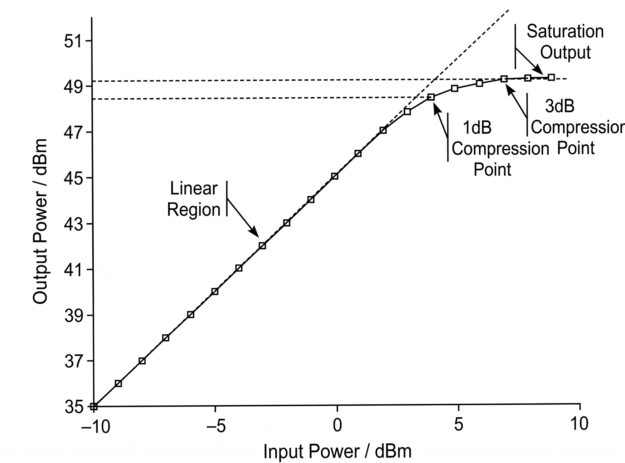
Understanding the 1dB Compression Point (P1dB)
The most common metric for this limit is the 1dB Compression Point, or P1dB2. This is the input power level at which the amplifier's gain drops by 1 dB from its ideal linear gain. Think of it as the ceiling for clean amplification. As you approach and exceed the P1dB, the top and bottom of your signal waveform get flattened, or "clipped." This clipping is a form of distortion. For my ground station, this meant the subtle phase and amplitude information in my modulated signal was being destroyed.
The Impact on Digital Modulation
Modern communication relies on complex modulation schemes like QAM (Quadrature Amplitude Modulation). These schemes encode data into tiny changes in the signal's amplitude and phase. We can visualize this on a constellation diagram, where each point represents a specific data symbol. In a clean, linear system, these points are sharp and distinct. But when the LNA saturates, it distorts the amplitude and phase. This causes the points on the diagram to smear and move from their ideal positions. The receiver can no longer tell which symbol was sent, leading to a massive increase in bit errors. That's exactly what I saw: a blurry mess instead of a clear constellation.
| Amplifier State | Output Waveform | Constellation Diagram | データの整合性 |
|---|---|---|---|
| Linear | Perfect replica | Sharp, distinct points | High (Low BER) |
| Non-Linear | Clipped, distorted | Smeared, blurry points | Low (High BER) |
How Do You Design an LNA System to Handle a Wide Dynamic Range?
Your ground station needs to handle both weak and strong satellite signals. But a single LNA often fails, being either too noisy for weak signals or saturating with strong ones. The solution is a balanced, multi-stage design.
Create a multi-stage LNA system. Use an amplifier with a very low noise figure (NF) in the first stage. Then, select a high OIP3 amplifier for the final stage to handle higher power. Place adjustable attenuators between stages to manage gain and prevent saturation.
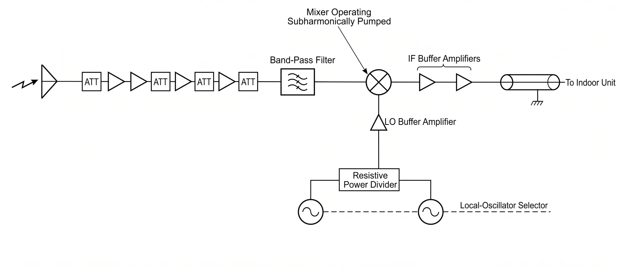
After realizing my single high-gain LNA was the problem, I redesigned my receiver front-end using a cascaded, multi-stage approach. This allowed me to optimize for different requirements at each point in the signal chain. This is the same principle we use at Safari Microwave when designing complex RF assemblies. We know that one size does not fit all. By breaking the problem down, I could finally get the performance I needed across all expected signal conditions.
Stage 1: Prioritizing Low Noise Figure (NF)
The overall noise figure of a receiver chain is dominated by the very first component. This is explained by the Friis formula for noise in cascaded systems3. So, for my first stage, the absolute priority was selecting an LNA with the lowest possible noise figure. I chose an LNA with an NF as low as 0.5 dB. This ensured that even the weakest signals were amplified above the system's noise floor without adding much noise of my own. I accepted a moderate gain for this stage because a super-high gain would have just made the saturation problem worse in the next stage. Products like our ultra-low NF LNAs, which can operate up to 110 GHz, are perfect for this critical first stage.
Stage 2: Dynamic Gain Control
cURL Too many subrequests by single Worker invocation. To configure this limit, refer to https://developers.cloudflare.com/workers/wrangler/configuration/#limits cURL Too many subrequests by single Worker invocation. To configure this limit, refer to https://developers.cloudflare.com/workers/wrangler/configuration/#limits cURL Too many subrequests by single Worker invocation. To configure this limit, refer to https://developers.cloudflare.com/workers/wrangler/configuration/#limits.
cURL Too many subrequests by single Worker invocation. To configure this limit, refer to https://developers.cloudflare.com/workers/wrangler/configuration/#limits
cURL Too many subrequests by single Worker invocation. To configure this limit, refer to https://developers.cloudflare.com/workers/wrangler/configuration/#limits cURL Too many subrequests by single Worker invocation. To configure this limit, refer to https://developers.cloudflare.com/workers/wrangler/configuration/#limits4. cURL Too many subrequests by single Worker invocation. To configure this limit, refer to https://developers.cloudflare.com/workers/wrangler/configuration/#limits.
| cURL Too many subrequests by single Worker invocation. To configure this limit, refer to https://developers.cloudflare.com/workers/wrangler/configuration/#limits | cURL Too many subrequests by single Worker invocation. To configure this limit, refer to https://developers.cloudflare.com/workers/wrangler/configuration/#limits | cURL Too many subrequests by single Worker invocation. To configure this limit, refer to https://developers.cloudflare.com/workers/wrangler/configuration/#limits | cURL Too many subrequests by single Worker invocation. To configure this limit, refer to https://developers.cloudflare.com/workers/wrangler/configuration/#limits |
|---|---|---|---|
| 1 | cURL Too many subrequests by single Worker invocation. To configure this limit, refer to https://developers.cloudflare.com/workers/wrangler/configuration/#limits | cURL Too many subrequests by single Worker invocation. To configure this limit, refer to https://developers.cloudflare.com/workers/wrangler/configuration/#limits | cURL Too many subrequests by single Worker invocation. To configure this limit, refer to https://developers.cloudflare.com/workers/wrangler/configuration/#limits |
| 2 | cURL Too many subrequests by single Worker invocation. To configure this limit, refer to https://developers.cloudflare.com/workers/wrangler/configuration/#limits | cURL Too many subrequests by single Worker invocation. To configure this limit, refer to https://developers.cloudflare.com/workers/wrangler/configuration/#limits | cURL Too many subrequests by single Worker invocation. To configure this limit, refer to https://developers.cloudflare.com/workers/wrangler/configuration/#limits |
| 3 | cURL Too many subrequests by single Worker invocation. To configure this limit, refer to https://developers.cloudflare.com/workers/wrangler/configuration/#limits | cURL Too many subrequests by single Worker invocation. To configure this limit, refer to https://developers.cloudflare.com/workers/wrangler/configuration/#limits | cURL Too many subrequests by single Worker invocation. To configure this limit, refer to https://developers.cloudflare.com/workers/wrangler/configuration/#limits |
cURL Too many subrequests by single Worker invocation. To configure this limit, refer to https://developers.cloudflare.com/workers/wrangler/configuration/#limits
cURL Too many subrequests by single Worker invocation. To configure this limit, refer to https://developers.cloudflare.com/workers/wrangler/configuration/#limits.
The most important metrics for an LNB's non-linearity budget are the 1dB Compression Point (P1dB), the Third-Order Intercept Point (IP3), and the Spurious-Free Dynamic Range (SFDR)5. These parameters define the power range where the LNB can operate linearly without significant distortion.

Digging into datasheets can be overwhelming. But once I understood my non-linearity problem, I knew exactly what to look for. These three metrics became my guide for selecting components and building a robust system budget. They tell a complete story about how an amplifier behaves under real-world conditions, where signals are strong, and multiple carriers are present. Understanding them is not just academic; it's essential for building a reliable communication link. At Safari Microwave, our 30 years of engineering experience have taught us that a 100% testing process focused on these specs is non-negotiable for stable and reliable performance.
P1dB: The Upper Limit of Linear Gain
As we discussed, the 1dB compression point (P1dB) marks the upper boundary of an amplifier's linear operating range. It tells you the power level at which you start to see significant gain compression. While you can technically operate an amplifier near its P1dB, it's a risky zone where distortion begins to creep in. A good rule of thumb is to design your system with a "back-off," ensuring your maximum expected signal power stays several dB below the amplifier's P1dB. This provides a safety margin against unexpected signal strength variations.
IP3: Predicting Intermodulation Distortion
The Third-Order Intercept Point (IP3) is a figure of merit that predicts how an amplifier will create intermodulation distortion (IMD). IMD occurs when two or more signals mix in a non-linear device, creating unwanted spurious signals close to the desired signals6. These "spurs" can interfere with adjacent channels or even corrupt your own signal. IP3 is a theoretical point where the power of the desired signal and the power of the third-order distortion products would be equal. A higher IP3 value means better linearity and less IMD. For the final LNA stage, a high OIP3 (Output IP3) is crucial. Our linear amplifiers, with their tight amplitude and phase matching, are designed to maximize this metric.
SFDR: The True Usable Range
Spurious-Free Dynamic Range (SFDR) is perhaps the most important single metric for a receiver. It defines the true usable "window" of operation. The bottom of this window is the noise floor (or minimum detectable signal), and the top is the maximum signal level you can handle before the distortion products (like IMD) rise above that same noise floor. A large SFDR means your system can process very weak signals and very strong signals without being compromised by either noise or distortion. It is the ultimate measure of a receiver's performance in a complex signal environment.
| Metric | What It Measures | Why It's Important |
|---|---|---|
| P1dB | Gain compression | Defines the maximum input power for quasi-linear operation. |
| IP3 | Intermodulation distortion | Predicts how much unwanted spurious signals will be generated. |
| SFDR | Usable power range | Shows the full range from noise floor to distortion limit. |
結論
Managing the LNB non-linearity budget is a balancing act. A multi-stage design that prioritizes low noise first and high linearity last is the key to a reliable satellite downlink.
"Characterizing the effects of nonlinear amplifiers on linear ...", https://ui.adsabs.harvard.edu/abs/1989gloc.conf...83A/abstract. A source can define gain compression and explain how the resulting non-linear amplification distorts the signal, degrading digital modulation performance (increasing BER) and creating unwanted IMD products. Evidence role: definition; source type: education. Supports: The claim that amplifier saturation causes signal compression, which in turn leads to waveform distortion, an increased bit error rate (BER), and the generation of intermodulation distortion (IMD).. ↩
"Compression point - Wikipedia", https://en.wikipedia.org/wiki/Compression_point. A source can define the P1dB as the input or output power level at which the amplifier's gain has decreased by 1 dB from its small-signal value, marking the onset of significant non-linearity. Evidence role: definition; source type: encyclopedia. Supports: The definition of the 1dB Compression Point (P1dB) as a standard metric for amplifier linearity.. ↩
"Friis formulas for noise - Wikipedia", https://en.wikipedia.org/wiki/Friis_formulas_for_noise. A source can present the Friis formula for noise figure, which shows that the noise contribution of each subsequent stage is divided by the cumulative gain of the preceding stages, making the first stage's noise figure the most significant contributor. Evidence role: definition; source type: encyclopedia. Supports: The claim that the overall noise figure of a cascaded system is determined primarily by the noise figure of the first stage.. ↩
"Third-order intercept point - Wikipedia", https://en.wikipedia.org/wiki/Third-order_intercept_point. A source can define OIP3 as a theoretical point on a graph of output power versus input power where the power of the desired signal and the power of the third-order distortion products are equal. A higher OIP3 value indicates a more linear amplifier. Evidence role: definition; source type: education. Supports: The definition of the Output Third-Order Intercept Point (OIP3) and its significance as a measure of amplifier linearity.. ↩
"Revisiting Spurious-Free Dynamic Range of Communication ...", https://ui.adsabs.harvard.edu/abs/2006ITCSR..53..937L/abstract. A source can define SFDR as the ratio of the root mean square (RMS) value of the carrier frequency to the RMS value of the next most significant spurious signal in the frequency spectrum. It represents the usable range of the receiver, free from distortion. Evidence role: definition; source type: education. Supports: The definition of Spurious-Free Dynamic Range (SFDR) as a key performance metric for receivers.. ↩
"Intermodulation - Wikipedia", https://en.wikipedia.org/wiki/Intermodulation. A source can explain that when two signals at frequencies f1 and f2 pass through a non-linear device, they create third-order intermodulation products at 2f1-f2 and 2f2-f1, which are often close to the original signals and can cause interference. Evidence role: mechanism; source type: encyclopedia. Supports: The claim that intermodulation distortion in a non-linear device creates spurious signals at frequencies adjacent to the input signals.. ↩
