
Torn between compact antenna size and raw BUC power? That compromise doesn't just degrade signal—it costs you contracts and cuts into your margins.
Matching BUC power with antenna size requires a precise RF link budget. Calculate your required EIRP, factor in the antenna gain (tied to its size), and select a BUC with enough power to overcome path loss, while staying within its linear operating range.
I recently had a conversation that many of you might find familiar. A client came to me with a request. "We need to shrink our antenna from 1.2 meters to 0.6 meters to cut costs," he said. "Can you just tweak some software parameters? We want to keep the same BUC." I had to explain that RF engineering isn't magic. The relationship between an antenna and a BUC is a system governed by strict rules. Let’s break down why this is so critical.
Why Can’t You Just Halve the Antenna Size and Keep the Same BUC?
Thinking of shrinking your antenna to save costs without changing your BUC? This decision can severely degrade your link performance, leading to connection failures and data loss.
Halving the antenna diameter reduces its gain by 6 dB1. If you keep the same BUC, your total radiated power (EIRP) drops significantly. This makes your signal much weaker, likely falling below the threshold needed for a stable connection, especially in adverse weather conditions.
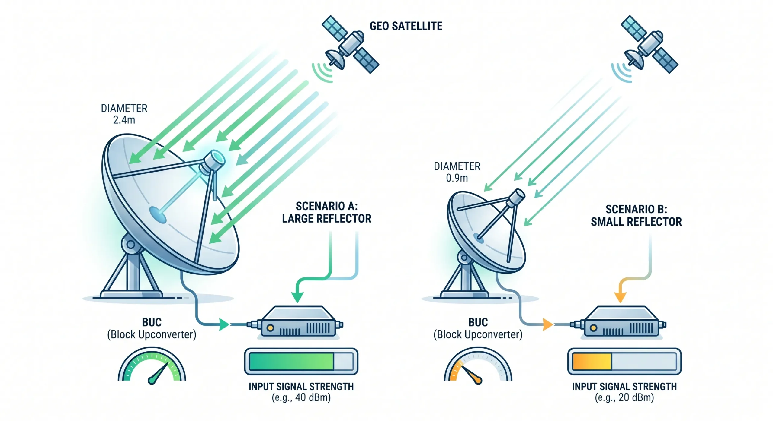
The relationship between an antenna's size and its gain is fundamental. Antenna gain is directly proportional to its effective aperture area2. When you reduce the diameter of a parabolic antenna by half, you are actually reducing its area by a factor of four. This translates to a significant loss in gain.
The Math Behind the Gain Loss
The formula for antenna gain is approximately [Gain (dB) ≈ 10 * log10(η * (πD/λ)^2)](https://en.wikipedia.org/wiki/Parabolic_antenna)3, where D is the diameter. A quick rule of thumb is that halving the diameter (D) results in a 6 dB loss of gain.
Let's see what that means for the system's EIRP (Effective Isotropic Radiated Power).
| Component | Original System (1.2m) | New System (0.6m) | Impact |
|---|---|---|---|
| Antenna Gain | G (dBi) | G - 6 dB | -6 dB |
| BUC Power | P (dBW) | P (dBW) | No Change |
| System EIRP | P + G (dBW) | P + G - 6 (dBW) | -6 dB |
A 6 dB drop in your link budget is massive. It could be the entire rain fade margin you designed for4, meaning your link will fail during the slightest drizzle. It's a system problem that requires a hardware solution, not a simple software fix.
How Do You Calculate the Right BUC Power for Your Antenna?
Are you unsure how much BUC power you truly need? Guessing can lead to overspending on overpowered units or suffering from an underperforming link. It’s a costly mistake.
Start with the satellite's required power density at its location. Work backward through your link budget, adding margins for free space loss, atmospheric absorption, and rain fade. The result tells you the required EIRP. Then, you can trade off between antenna gain and BUC power.
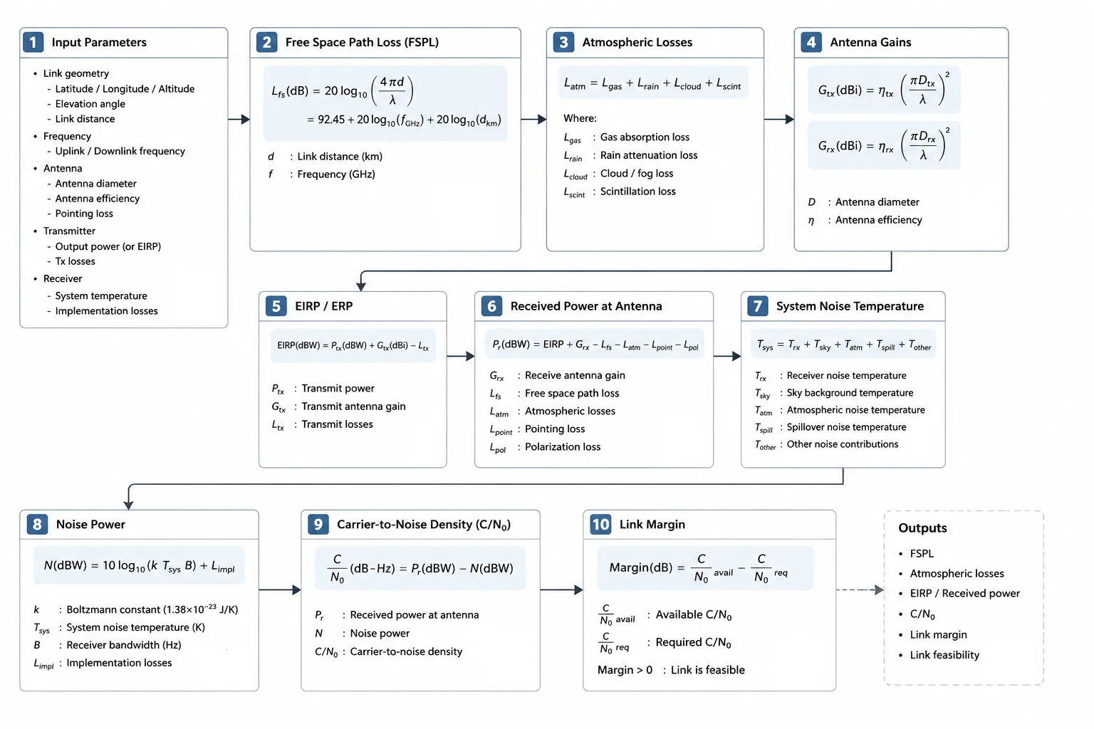
The core of this process is the RF link budget. It’s a simple accounting of all the gains and losses in your signal path from the transmitter to the receiver. The goal is to ensure the received signal power is above the receiver's sensitivity threshold with a healthy margin.
Building a Simplified Uplink Budget
You need to calculate the required EIRP from your ground station. This is the starting point for choosing your BUC and antenna combination. Here's a simplified breakdown:
- Start at the Satellite: The satellite operator will specify the power level they need to receive (e.g., -120 dBW/m²).
- Add Path Losses: This is the biggest loss factor. It includes free space path loss (FSPL), which depends on frequency and distance, and atmospheric losses (gases, clouds, rain). Always add a margin for rain fade based on your location's climate and desired link availability (e.g., 99.9%).
- Calculate Required EIRP: The sum of the required satellite power and all path losses gives you the total EIRP you must transmit.
| Parameter | Example Value | Notes |
|---|---|---|
| Required Power at Satellite | -90 dBW | From satellite operator |
| Free Space Path Loss (FSPL)5 | 205 dB | For Ku-band, GEO satellite |
| Rain Fade Margin | 5 dB | For 99.9% availability |
| Required EIRP | 120 dBW | (-90 + 205 + 5) |
Once you know your required EIRP (e.g., 120 dBW), you can find the right BUC/antenna pair. A 1.2m antenna with 42 dBi gain would need a BUC with 120 - 42 = 78 dBW of power. A smaller 0.6m antenna with 36 dBi gain would need a BUC with 120 - 36 = 84 dBW of power. That's four times the power!
Why Does Signal Modulation Affect Your BUC Power Choice?
You've calculated your required power, but your link is still unstable. The problem might be signal modulation causing non-linear distortion, creating errors and wasting power.
Modern, high-data-rate modulations have a high Peak-to-Average Power Ratio (PAPR)6. Driving your BUC too close to its maximum (saturated) power can clip these peaks, causing distortion and spectral regrowth7. You must back off the power to ensure the BUC operates in its linear region.

A BUC is a power amplifier, and not all power is created equal. Amplifiers have a linear region where the output is a faithful, magnified copy of the input. They also have a saturated region where they can't produce any more power. Pushing an amplifier into saturation clips the signal.
Understanding PAPR and Back-off
Simple modulations like BPSK have a low PAPR. But complex, higher-order modulations like 16QAM or 64QAM, used for high-speed data, have high peaks in their waveform. The ratio of these peaks to the average power is the PAPR.
If your average power is set too high, these peaks will push the BUC into saturation.
| Modulation Scheme | Typical PAPR | Required Power Back-off | Consequence of No Back-off |
|---|---|---|---|
| QPSK | ~3-4 dB | 2-3 dB | Minor distortion |
| 16QAM | ~5-7 dB8 | 4-5 dB | Significant bit errors, spectral regrowth |
| 64QAM | ~7-9 dB | 6-7 dB9 | Unusable link, interference with adjacent channels |
This means if you need 10W of linear power for your 16QAM signal, you can't just buy a 10W BUC. You need a BUC rated for much higher saturated power, perhaps 25W or 40W, and then "back it off" to operate at 10W average power. This ensures even the highest peaks are amplified cleanly. Ignoring this is a classic mistake that leads to unstable links.
How Can You Get More Power Without Compromising Linearity?
Need more power but worried about distortion and size? Standard BUCs force you to choose between high power and clean signals, limiting your system's performance and flexibility.
Advanced BUCs, like our 3000W saturated power amplifier, are designed for high efficiency and linearity. They provide the headroom needed for complex modulations and allow you to use smaller antennas while maintaining a robust link margin, even in challenging conditions.

As we've seen, matching BUC power and antenna size is a delicate balance involving physics and budget. My company, Safari Microwave, specializes in creating components that give you more flexibility in this balancing act. For over 30 years, our engineering team has been designing and perfecting RF components for demanding applications.
The Safari Microwave Advantage
Take the scenario with the smaller antenna. Instead of being stuck, you need a BUC with more linear power. Our product line is designed for exactly these challenges.
- High Power for Smaller Antennas: Our 3000-watt saturated power amplifier provides immense headroom. You can easily achieve the high linear power required for a 0.6m antenna, even with complex modulation schemes. Its premium efficiency also helps manage power consumption.
- Ultra-Wideband Performance: Many of our amplifiers, including linear models reaching 110GHz, offer ultra-wideband performance. This allows you to adapt your system to different frequency bands without swapping hardware, providing long-term value.
- Guaranteed Reliability: We understand that in your business, downtime is not an option. That's why every single one of our products undergoes 100% full inspection. Our 30 years of engineering experience is built into every component we ship, ensuring stable and reliable performance. We are the trusted source for major defense contractors and telecom operators worldwide for a reason.
Conclusion
Matching your BUC and antenna isn't guesswork. It requires a proper link budget that accounts for gain, power, and modulation to ensure a reliable and efficient system.
"Parabolic Reflector Antenna Gain Calculator - everything RF", https://www.everythingrf.com/rf-calculators/parabolic-reflector-antenna-gain. A source can confirm the mathematical relationship between a parabolic antenna's diameter and its gain, showing that because gain is proportional to the area (which is proportional to the square of the diameter), halving the diameter reduces the gain by a factor of four, which corresponds to approximately 6 dB (10*log10(0.25) ≈ -6.02). Evidence role: mechanism; source type: education. Supports: The relationship between an antenna's diameter and its gain, specifically that halving the diameter results in a four-fold reduction in area and a corresponding 6 dB loss in gain.. ↩
"Aperture (antenna) - Wikipedia", https://en.wikipedia.org/wiki/Aperture_(antenna). An academic or reference source can define antenna gain and effective aperture, confirming that gain is a measure of directivity and is directly proportional to the antenna's effective area. Evidence role: definition; source type: encyclopedia. Supports: The definition of antenna gain and its direct proportionality to the effective aperture area of the antenna.. ↩
"Parabolic antenna - Wikipedia", https://en.wikipedia.org/wiki/Parabolic_antenna. A source from an educational institution or an engineering handbook can provide the standard formula for calculating the gain of a reflector antenna, defining each variable and explaining its role in the calculation. Evidence role: definition; source type: education. Supports: The standard formula for calculating the gain of a parabolic antenna, including definitions for diameter (D), wavelength (λ), and aperture efficiency (η).. ↩
"[PDF] RECOMMENDATION ITU-R P.838-3 - Specific attenuation model for ...", https://www.itu.int/dms_pubrec/itu-r/rec/p/r-rec-p.838-3-200503-i!!pdf-e.pdf. A source, such as an ITU recommendation or a satellite communication engineering guide, can provide examples of link budgets showing that rain fade margins in the range of 3-8 dB are common for Ku-band links, depending on location and required availability, thus supporting the claim that a 6 dB loss is significant. Evidence role: statistic; source type: institution. Supports: That a rain fade margin of around 6 dB is a plausible value for a satellite link, for example, a Ku-band link in a moderate climate aiming for 99.9% or 99.95% availability.. Scope note: The exact rain fade margin is highly dependent on geographic location, frequency, and desired link availability. ↩
"Free-space path loss - Wikipedia", https://en.wikipedia.org/wiki/Free-space_path_loss. A reference source can define Free Space Path Loss as the loss in signal strength of an electromagnetic wave that would result from a line-of-sight path through free space, and provide the standard formula FSPL (dB) = 20log10(d) + 20log10(f) + 20log10(4π/c) - Gt - Gr. Evidence role: definition; source type: encyclopedia. Supports: The definition of Free Space Path Loss (FSPL) and the formula used to calculate it, which shows its dependence on frequency and distance.. ↩
"What is Peak-To-Average Power Ratio? - everything RF", https://www.everythingrf.com/community/what-is-peak-to-average-power-ratio. A reference source can define PAPR as the ratio of the peak power to the average power of a signal and explain that modulation schemes like 16QAM and 64QAM, which have more possible amplitude levels, typically exhibit higher PAPR than simpler schemes like BPSK or QPSK. Evidence role: definition; source type: encyclopedia. Supports: The definition of Peak-to-Average Power Ratio (PAPR) and the principle that more complex, multi-level modulation schemes tend to have higher PAPR than simpler schemes.. ↩
"Nonlinearity estimation and spectral regrowth prediction of power ...", https://ui.adsabs.harvard.edu/abs/2005wami.conf...41L/abstract. A technical paper or application note on power amplifier linearity can explain that when an amplifier is driven into saturation, the resulting signal clipping and distortion generate new frequency components outside the signal's intended bandwidth, a phenomenon known as spectral regrowth, which can cause adjacent channel interference. Evidence role: mechanism; source type: paper. Supports: The phenomenon of spectral regrowth, where the non-linear characteristics of a saturated power amplifier cause the output signal's spectrum to spread into adjacent frequency bands.. ↩
"Comparisons of 16QAM Modulation Schemes Considering PAPR for ...", https://ieeexplore.ieee.org/document/4100578/. A technical paper or engineering reference can show that while theoretical PAPR for 16QAM can be calculated, practical measurements for filtered signals typically fall within the 5-7 dB range, depending on the specific implementation and filtering. Evidence role: statistic; source type: paper. Supports: The typical PAPR value for 16QAM modulation.. Scope note: The exact PAPR can vary based on the pulse-shaping filters and other parameters of the transmission system. ↩
"Higher Order Modulation - an overview | ScienceDirect Topics", https://www.sciencedirect.com/topics/engineering/higher-order-modulation. An application note or research paper on power amplifier linearization can support this by explaining that to accommodate the high PAPR of 64QAM (typically 7-9 dB), a back-off of a similar magnitude (e.g., 6-7 dB) from the amplifier's saturation point is necessary to ensure the signal peaks are not clipped. Evidence role: general_support; source type: research. Supports: The need for significant power back-off when using high-order modulation schemes like 64QAM to keep the amplifier in its linear region and avoid distortion.. Scope note: The exact required back-off depends on the specific amplifier's characteristics and the acceptable level of distortion or spectral regrowth for the system. ↩
