
Your satellite system is plagued by interference, and you think a perfect filter is the answer. But demanding impossible specs wastes time and money, derailing your project before it even starts.
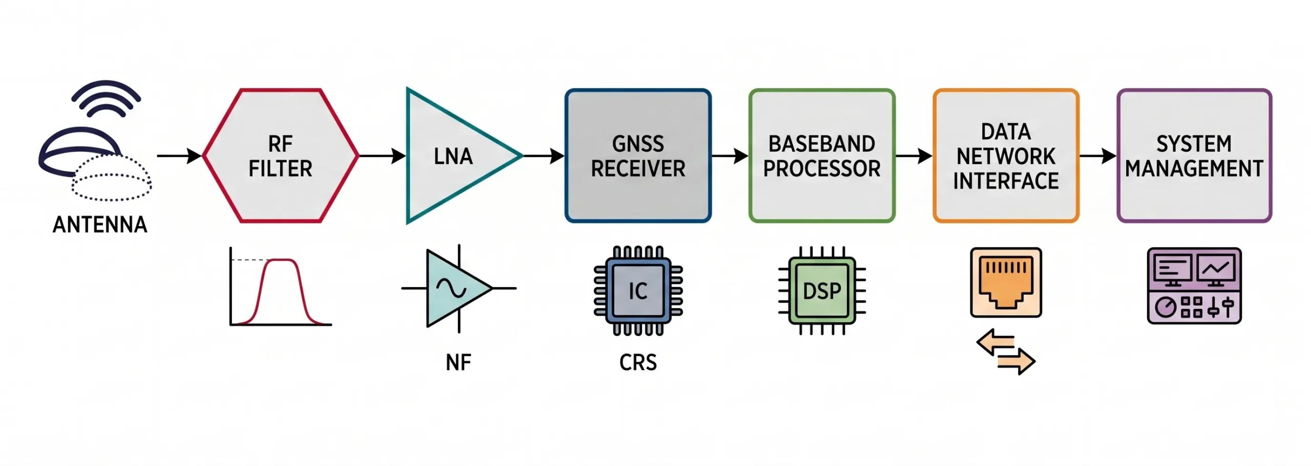
An RF filter in a satellite ground station is an electronic component that selects desired signal frequencies and rejects unwanted ones.1 It works like a gatekeeper, using resonant circuits to let your specific satellite channel pass through while blocking all other signals, like noise and interference.
As an RF engineer, I often get requests that sound simple but are physically impossible. I once had a client ask me to design a bandpass filter for a satellite project. "I need it to pass 2120-2200 MHz," he said, "but it must have more than 70 dB of rejection at 2100 MHz because of strong interference there." I had to tell him that the filter he wanted only exists in theory. Even a perfect simulation can't predict all the real-world problems that come up during tuning, often because of tiny, unseen parasitic effects from the components themselves. To build a robust system, you need to understand the real-world limits of these critical components. Let's dive into what makes a filter work, and what makes it fail.
What are the Key Parameters of a Real-World RF Filter?
You focused on your filter's passband, but system performance is still poor. This happens when critical parameters are overlooked, degrading your entire signal chain and causing unexpected issues.
The key parameters are passband, stopband, insertion loss, return loss (VSWR), and rejection.2 These metrics define how well a filter passes the signals you want and blocks the signals you don't in a practical, real-world application.
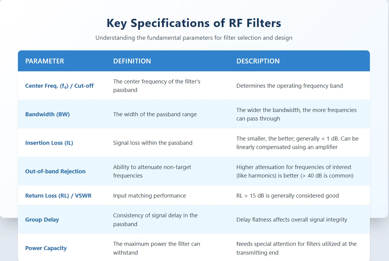
When you are specifying a filter, you need to look beyond just the frequencies it passes and blocks. The true performance is in the details. A filter that looks good on paper can bring a system to its knees if these other parameters are not properly considered. I've seen projects delayed for weeks because a filter had slightly too much loss or a poor match, causing a ripple effect across the entire system. Understanding each parameter helps you write a specification that is both effective and achievable.
Passband and Stopband
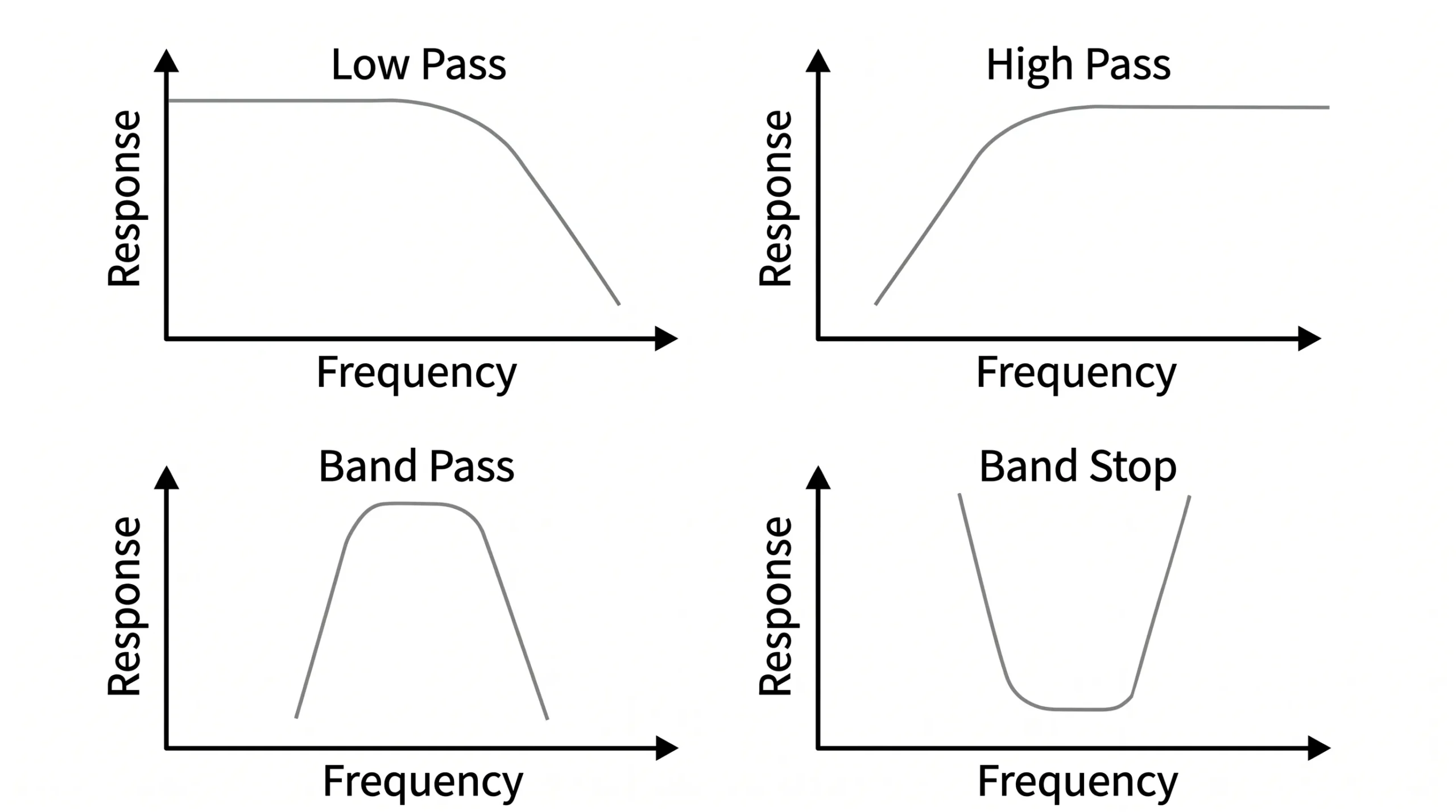
The passband is the range of frequencies the filter is designed to let through with minimal opposition. The stopband is the range of frequencies it is designed to block or attenuate. The area between them is the transition band.
Insertion Loss and Return Loss
Insertion Loss (IL) is the amount of signal strength lost as it travels through the filter's passband. Lower is always better. Return Loss measures the signal reflected back from the filter due to impedance mismatch. High return loss is good, as it means most of the signal is passing through, not bouncing back. It is often expressed as VSWR, where a value close to 1:1 is ideal.
Rejection and Selectivity
Rejection (or attenuation) specifies how much the filter blocks signals in the stopband. Selectivity describes how sharp the transition is from the passband to the stopband. A "sharper" filter has better selectivity.
Here is a table comparing ideal goals with what we often see in reality.
| Parameter | Ideal "Textbook" Filter | Real-World Filter | My Experience Notes |
|---|---|---|---|
| Insertion Loss | 0 dB | 0.5 dB - 5 dB+ | Higher rejection almost always means higher insertion loss. |
| Return Loss / VSWR | ∞ dB / 1:1 | 10-20 dB / < 2:1 to 1.2:1 | A bad match (low return loss) can damage amplifiers upstream. |
| Transition Band | 0 Hz wide (a cliff) | Varies (can be wide) | The "brick-wall" filter is a myth. This is where costs add up. |
| Stopband Rejection | ∞ dB | 30 dB - 90 dB | Achieving over 70 dB requires very complex, expensive designs. |
Why Do Ideal "Brick-Wall" Filters Only Exist in Theory?
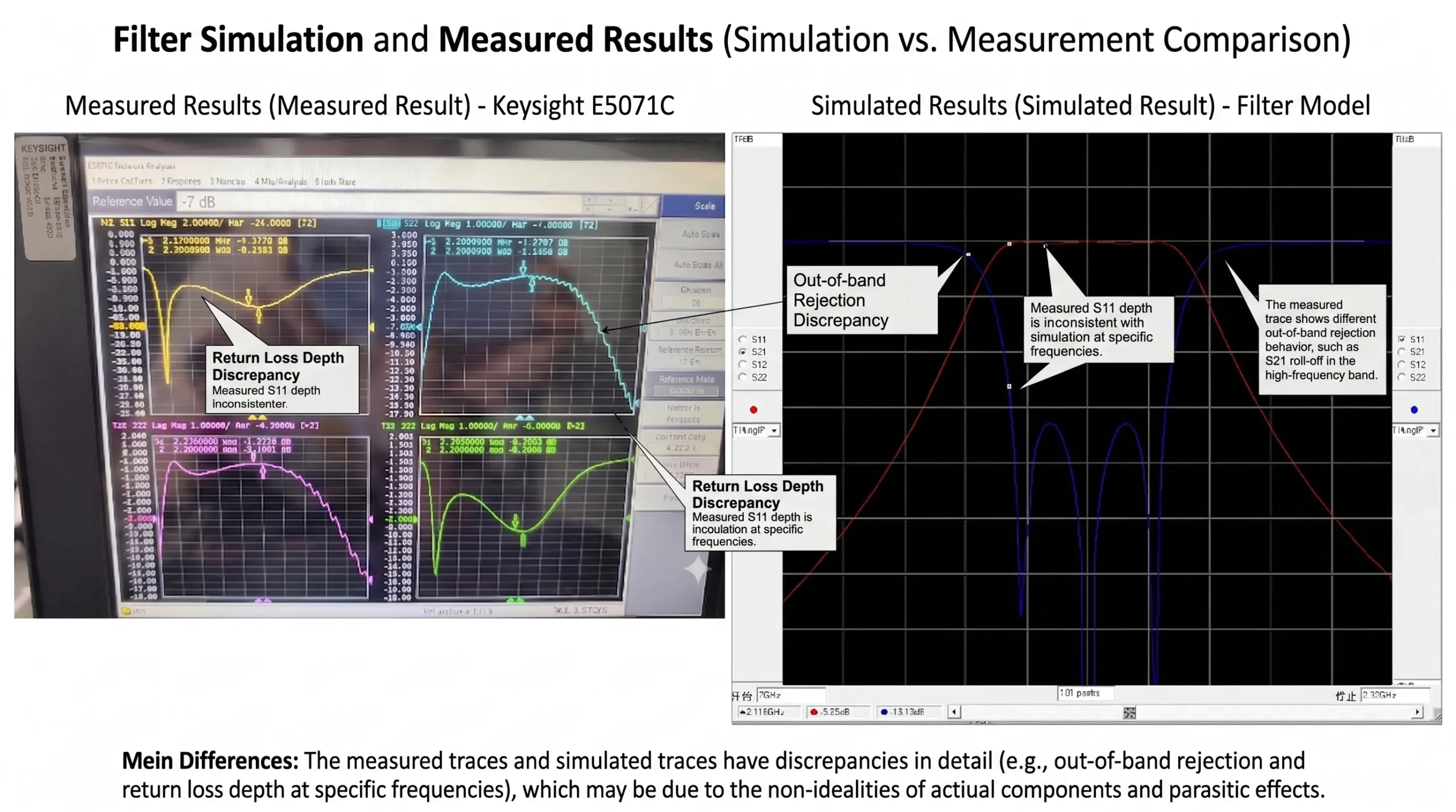
You designed a perfect filter in your simulation software, but the physical prototype fails miserably. This frustration comes from the gap between the clean world of simulation and messy physical reality.
Ideal "brick-wall" filters with infinitely sharp cutoffs are physically impossible. Every real-world component, like a capacitor or inductor, has parasitic properties that limit performance and prevent the perfectly sharp transitions seen in software models.
That request I mentioned—a filter passing 2120-2200 MHz with >70 dB rejection at 2100 MHz—is a perfect example of this challenge. The client wanted a massive 70 dB drop in just a 20 MHz transition band (from 2120 MHz down to 2100 MHz). This is incredibly difficult. To get that kind of sharp cutoff, you need a filter with a very high "order," meaning it has many resonant sections. But adding more sections is not a simple fix. It creates a domino effect of problems.
The Problem of Sharp Transitions
A sharp transition requires a high-order filter.3 However, each additional section in the filter adds to its insertion loss, making your desired signal weaker. It also increases group delay variation, which can distort signals with complex modulation, a common issue in modern satellite communications.
Parasitic Effects in Components
In the real world, an inductor has some capacitance, and a capacitor has some inductance. These are called "parasitics." At microwave frequencies, these tiny, unwanted effects create their own resonance paths, smearing the filter's response and preventing a clean, sharp cutoff. This is often what separates a beautiful simulation from a disappointing physical device.
The Quality Factor (Q)
The Quality Factor, or Q, of the filter's resonators dictates how sharp it can be.4 Higher Q allows for better selectivity and lower insertion loss. However, materials and manufacturing techniques limit how high the Q can be. This physical limit is a primary reason why "brick-wall" performance is not achievable.
This table shows the trade-offs you face when trying to achieve a sharper filter response:
| If You Increase... | Sharpness (Selectivity) | Insertion Loss | Size & Complexity | Cost |
|---|---|---|---|---|
| Filter Order | Increases | Increases | Increases | Increases |
| Resonator Q-Factor | Increases | Decreases | May Increase | Increases |
How Do You Choose the Right Filter Type for Your Satellite Application?
You need to eliminate a strong nearby signal, but which filter should you use? Choosing the wrong topology can be a costly mistake, wasting valuable time and compromising system performance from the start.
The choice depends on your specific goal. Use a band-pass filter to isolate a satellite channel, a low-pass to remove harmonics from an amplifier, or a band-stop to notch out a known interferer like a 5G signal.
In a satellite ground station, you are not just dealing with one signal. You have your desired downlink, your uplink, and a whole spectrum of potential interference from terrestrial services like cellular towers, radar, and other satellites. Each problem requires a specific tool. Trying to use a single, all-purpose filter is inefficient and often ineffective. As a company that designs and manufactures these components, we help customers navigate these choices every day. The key is to first identify the exact problem you are trying to solve.
Filter Types and Their Jobs
- Low-Pass Filter (LPF): Passes all frequencies from DC up to a certain cutoff frequency. It is perfect for removing unwanted harmonics generated by power amplifiers.
- High-Pass Filter (HPF): Passes all frequencies above a certain cutoff frequency. Useful for blocking low-frequency noise or unwanted intermediate frequencies (IF).
- Band-Pass Filter (BPF): Passes only a specific range of frequencies. This is the most common type in a receiver front-end, used to select the desired satellite channel. Our high-power, ultra-wideband amplifiers often get paired with these.
- Band-Stop Filter (BSF): Also called a "notch" filter, this blocks a specific range of frequencies. It is the ideal solution for eliminating a known, narrow source of interference.
Here is a guide for matching common ground station issues to the right filter solution:
| Common Problem | Description | Recommended Filter Type | Why It Works |
|---|---|---|---|
| Harmonic Interference | Your high-power amplifier (HPA) is creating multiples of your uplink frequency. | Low-Pass Filter (LPF) | It passes your fundamental frequency but attenuates the higher-order harmonics. |
| 5G Interference in C-Band | A nearby 5G tower is bleeding into your C-band satellite downlink (3.7-4.2 GHz). | Band-Pass Filter (BPF) | A sharp BPF isolates the satellite band and strongly rejects the adjacent 5G signals. |
| Selecting a Single Channel | You need to process one specific transponder channel from a wide satellite band. | Band-Pass Filter (BPF) | A narrow BPF selects only the channel you want, improving signal-to-noise ratio. |
| Known Interfering Signal | A continuous-wave (CW) signal from a local source is disrupting your system. | Band-Stop Filter (BSF) | It creates a deep "notch" at the exact frequency of the interferer, removing it. |
What Challenges Arise When Integrating a Filter into Your RF System?
Your new filter performs perfectly on the test bench. But once you connect it to your amplifier and mixer, the entire system's performance drops. This is the integration nightmare.
The biggest challenge is impedance mismatch between the filter and adjacent components. This mismatch causes signal reflections (high VSWR), which increases loss, creates passband ripple, and can even degrade the performance of other parts in the chain.
A filter never works in isolation. It is part of a chain that might include an LNA, a mixer, a power amplifier, and antennas. Every connection point is a potential point of failure. I remember a project involving an outdoor ground station in a desert region. The filter we initially chose worked great in the lab, but its performance drifted wildly as the temperature swung from day to night. The impedance changed with the heat, ruining the system's passband. We had to redesign it using a more stable cavity filter technology to meet the client's tough environmental requirements. This experience taught me that integration is as important as the component itself.
The Impedance Matching Nightmare
Most RF systems are designed for a 50-ohm impedance.5 If a filter does not present a perfect 50-ohm load, signals will reflect off its input and output ports. This creates standing waves (measured as VSWR) and can cause the filter's carefully designed passband to become wavy and uneven.
Thermal Stability and Power Handling
As seen in my story, temperature affects the physical dimensions of filter components, which in turn changes their electrical performance. For high-power applications, like at the output of a 3000W BUC, the filter must also be able to handle that power without overheating or breaking down. Our high-power PIN diode switches and power dividers face similar thermal challenges, which is why robust design is critical.
Manufacturing Tolerances and Size
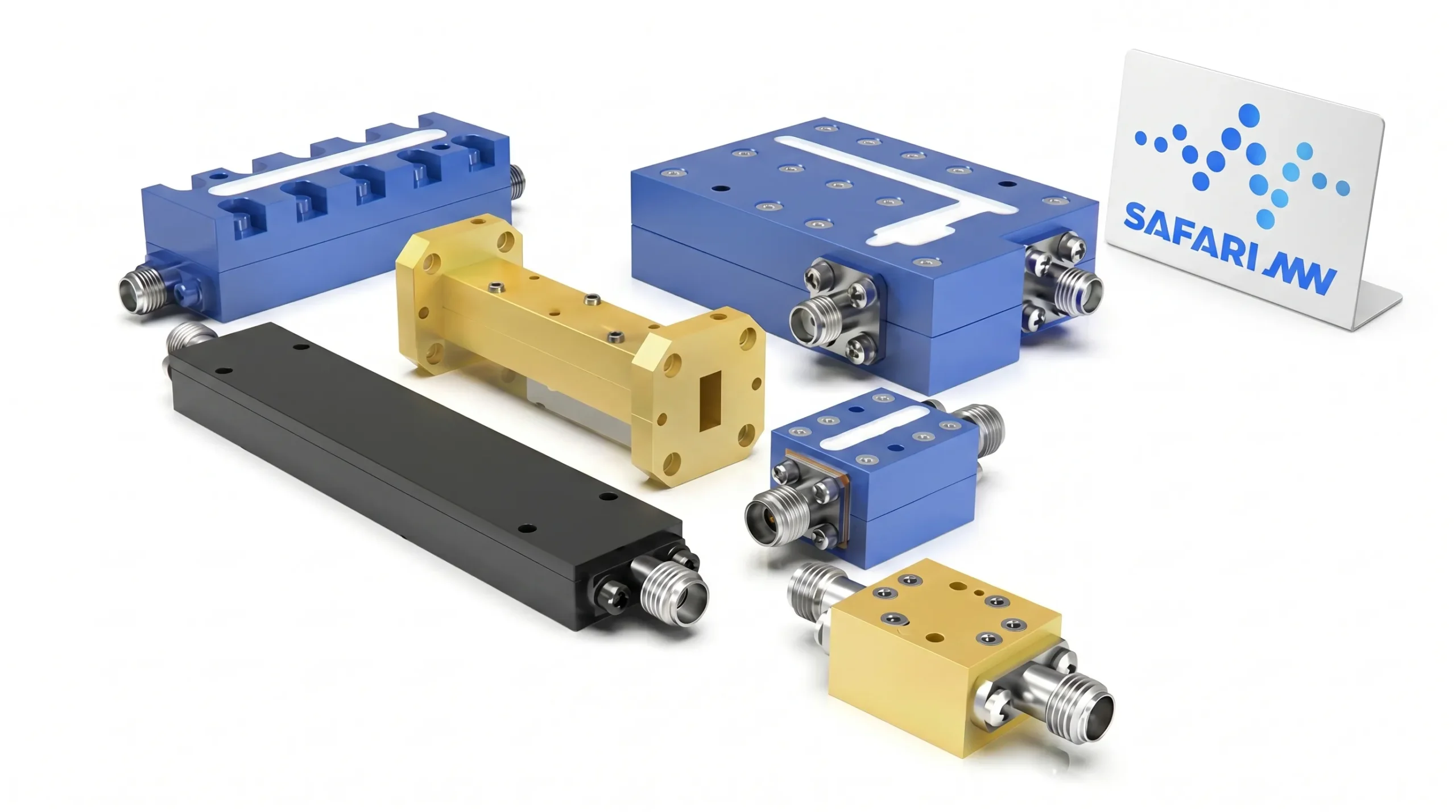
Even with a great design, slight variations in manufacturing can cause one filter to perform differently from the next.6 At Safari Microwave, we address this with 100% testing to ensure every component meets its spec. Furthermore, a high-performance filter can be physically large, especially at lower frequencies, creating layout challenges on a crowded system board.
These are the real-world problems that separate a catalog component from a truly integrated, reliable solution. It requires a deep understanding of the entire system, not just the filter.
Conclusion
Understanding a filter's real-world limits is crucial.7 It helps you set achievable specifications and build a reliable satellite communication system that works not just in theory, but in the field.
"Comprehensive Guide to RF Filters: Types and Uses - Q Microwave", https://en.wikipedia.org/wiki/RF_and_microwave_filter. RF filters are electronic components used in satellite ground stations to select desired signal frequencies while rejecting unwanted ones, as described in technical literature on RF systems. Evidence role: definition; source type: education. Supports: Defines the function of RF filters in satellite ground stations.. ↩
"FILT8-2 - Filters: Introduction, definition of terms, Q&As - Mini-Circuits", https://www.minicircuits.com/appdoc/FILT8-2.html?srsltid=AfmBOooyATeHW9GDjR8ZrdZKrfzMATRasRYQnrx21HtIhekrvqFWIs0E. Passband, stopband, insertion loss, return loss (VSWR), and rejection are standard parameters used to evaluate RF filter performance. Evidence role: definition; source type: education. Supports: Identifies the key performance parameters of RF filters.. ↩
"What is the relation of the transition band's width and the filter order ...", https://dsp.stackexchange.com/questions/96241/what-is-the-relation-of-the-transition-bands-width-and-the-filter-order-for-the. Higher-order filters are designed with multiple resonant sections, enabling sharper transitions between passband and stopband. Evidence role: mechanism; source type: education. Supports: Describes how higher-order filters achieve sharper transitions.. ↩
"Q factor - Wikipedia", https://en.wikipedia.org/wiki/Q_factor. The Q-factor of a filter's resonators directly impacts its selectivity and sharpness, as higher Q values allow for narrower bandwidths. Evidence role: mechanism; source type: education. Supports: Explains the relationship between the Q-factor of resonators and the sharpness of RF filters.. ↩
"The Mysterious 50 Ohm Impedance: Where It Came From and Why ...", https://resources.altium.com/p/mysterious-50-ohm-impedance-where-it-came-and-why-we-use-it. The 50-ohm impedance standard is widely used in RF systems to balance power handling and signal loss. Evidence role: expert_consensus; source type: education. Supports: Confirms that 50-ohm impedance is a standard design parameter in RF systems.. ↩
"Millimeter Wave Filter Manufacturing: Tolerance and Size", https://blog.knowlescapacitors.com/blog/millimeter-wave-filter-manufacturing-tolerance-and-size. Variations in manufacturing tolerances can lead to differences in the performance of RF filters, even within the same design. Evidence role: mechanism; source type: research. Supports: Explains how manufacturing tolerances affect the performance consistency of RF filters.. ↩
"Perspectives on setting limits for RF contact currents: a commentary", https://pmc.ncbi.nlm.nih.gov/articles/PMC5769355/. Considering real-world limitations, such as parasitics and manufacturing tolerances, is essential for designing reliable RF systems. Evidence role: general_support; source type: education. Supports: Highlights the importance of understanding real-world limitations in RF filter design.. ↩
