
Finding the S-parameter formulas in textbooks too abstract? This lack of clarity can keep you from fully grasping RF measurements1. Everything clicks once you learn how a Vector Network Analyzer (VNA)2 operates.
A Vector Network Analyzer (VNA) measures S-parameters3 by sending a known signal to a device's port. It then measures the reflected signal from that same port and the transmitted signals at all other ports. It compares the magnitude and phase of these signals to the original incident signal.
I remember when I was a junior RF engineer. The S-parameter equations felt disconnected from my work on the bench. It wasn't until I stopped thinking of the VNA as a magic box and started learning about its internal structure that everything clicked. This understanding was a turning point for me. It transformed how I interpreted measurement results and designed circuits. Let’s open up this "box" together and see how this powerful machine gives us the S-parameters we rely on every day.
What is the basic principle behind a Vector Network Analyzer?
VNAs can seem like very complex black boxes. This feeling makes you think you are just pushing buttons without really understanding what is happening inside. But the main idea is simple: send a signal and measure what comes back.
A VNA's principle is to generate a precise RF signal and route it to the device under test (DUT)4. It uses internal directional couplers to separate incident, reflected, and transmitted waves. Receiver5s then measure the magnitude and phase of these waves relative to the source signal.
To really get it, let's look at the key parts inside a VNA and what they do. The whole process is a well-coordinated sequence of events that happens very quickly across a range of frequencies. The VNA sweeps its source frequency and repeats these measurements at each point to draw the familiar S-parameter graphs we see on the screen. It is this internal hardware that turns abstract theory into concrete, usable data for engineers like us.
Key VNA Components
The magic of a VNA comes from a few core components working together. Each one has a specific job in the measurement process.
| Component | Function |
|---|---|
| RF Source | Generates a very stable and precise sine wave at a specific frequency and power level. |
| Directional Coupler6 | A special component that can separate signals based on their direction of travel. It's the key to isolating the reflected wave from the incident wave. |
| Receivers | Highly sensitive detectors that measure the magnitude and phase of the RF signals captured by the couplers. They compare these signals to the original source signal. |
| Processor/Display | Takes the raw data from the receivers and calculates the S-parameters, then displays them in various formats (Log Mag, Smith Chart7, etc.). |
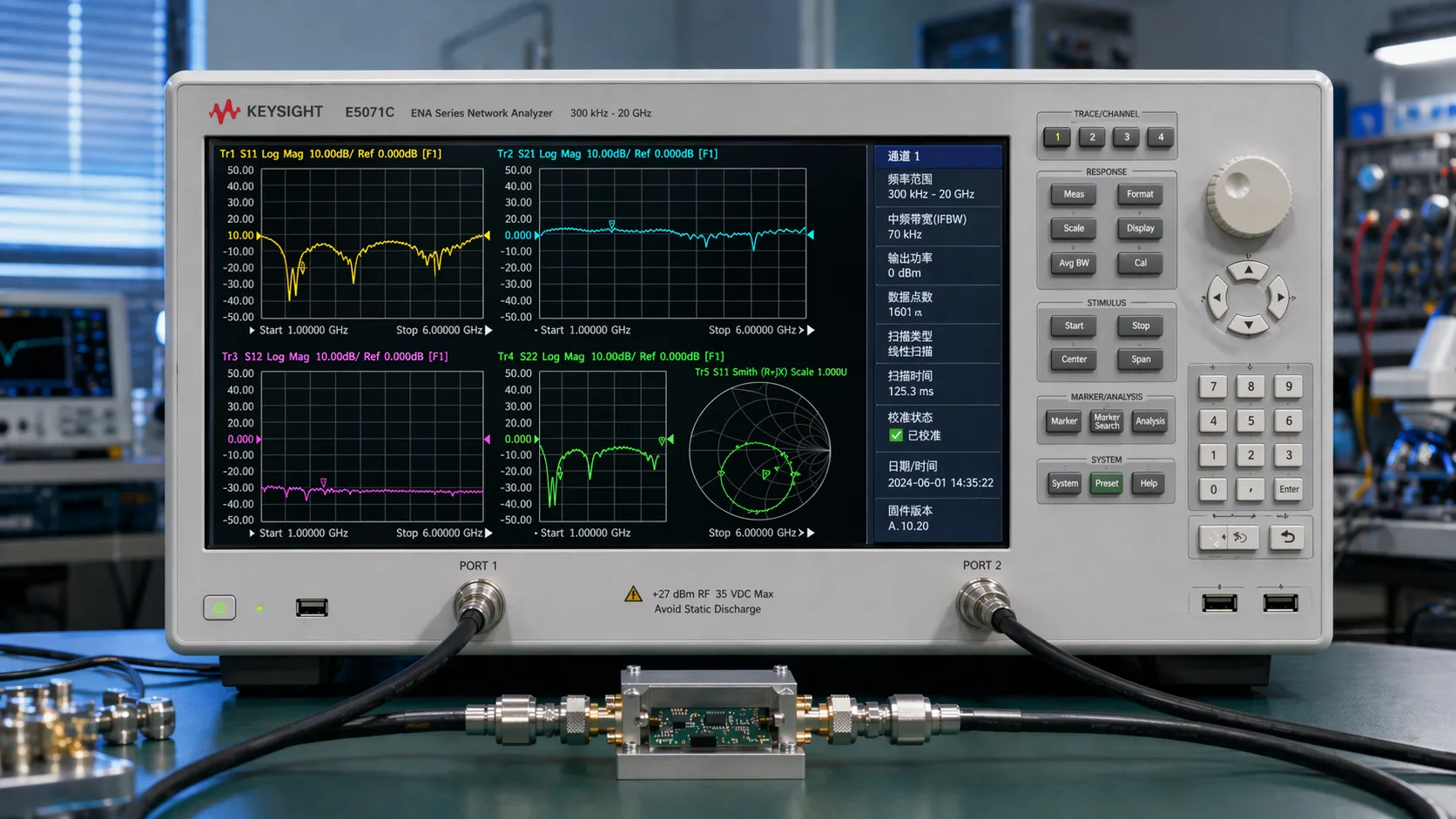
How does a VNA measure reflected signals like S11?
Understanding return loss or VSWR from a measurement can be tricky. If you don't understand it, you can't be sure if your device is properly matched to the system. So, let's see how a VNA specifically measures the reflection, S11.
To measure S11, the VNA sends a signal to Port 1 of the DUT. A directional coupler inside the VNA separates the signal reflected from Port 1. The VNA's receiver then compares the magnitude and phase of this reflected signal to the original incident signal.
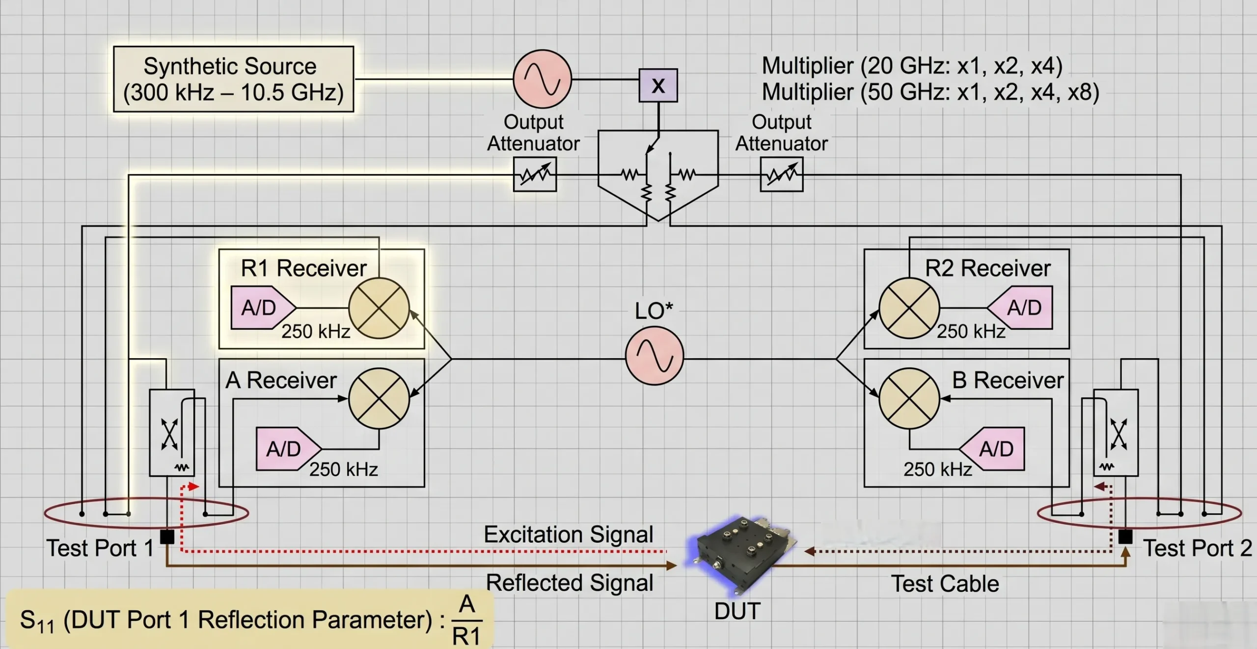
The measurement of S11, or input return loss, is fundamental. But the raw measurement is useless without proper calibration. This is a critical step that many junior engineers can overlook. I remember my first time trying to match an antenna. Seeing the S11 dip on the VNA screen after each small adjustment was a 'eureka' moment. It made the theory real. That visual feedback is only possible because of a good calibration.
The Role of Calibration
Before you measure your device, you must perform a calibration. The most common type is SOLT (Short, Open, Load, Thru). This process essentially teaches the VNA what perfect and imperfect electrical conditions look like at the exact ends of your test cables.
- Short: A short circuit reflects all power with a 180-degree phase shift.
- Open: An open circuit reflects all power with a 0-degree phase shift.
- Load: A perfect 50-ohm load absorbs all power, so there is no reflection.
- Thru: This connects the two test cables together to characterize the loss of the cables themselves.
By measuring these known standards, the VNA creates a mathematical model. It uses this model to remove the effects of cables and connectors from your DUT measurement. This is how we get an accurate S11 reading of just the device itself.
How does a VNA measure transmitted signals like S21?
You need to know how much gain or loss your amplifier or filter has. Just looking at a number on the screen is not enough. You need to trust that the measurement is accurate. Understanding the S21 measurement process builds that trust.
To measure S21, the VNA sends a signal to Port 1 of the DUT. The signal travels through the device and exits at Port 2. A receiver connected to Port 2 measures the magnitude and phase of this transmitted signal, comparing it to the original incident signal from Port 1.
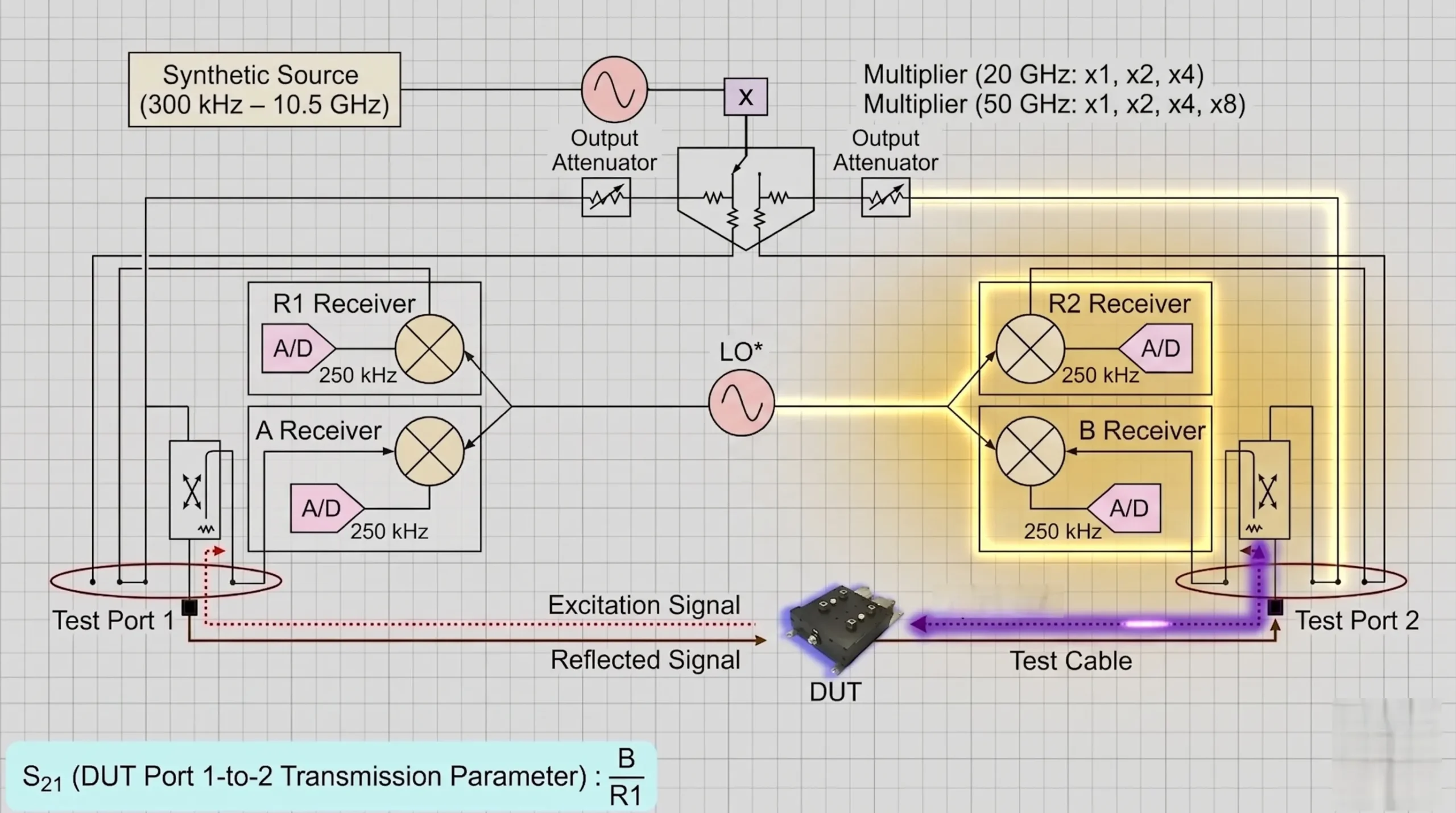
The measurement of S21, or forward transmission, tells us what happens to a signal as it passes through a device. For an amplifier, we expect S21 to be greater than 0 dB, which indicates gain. For a filter or a cable, we expect S21 to be less than 0 dB, which indicates insertion loss. The VNA's ability to measure both the change in power (magnitude) and the change in timing (phase) is what makes it so powerful. This is critical for characterizing advanced components like our high-power amplifiers or phase-balanced power dividers, where phase matching is just as important as amplitude.
What S-parameters Tell Us
For a standard two-port device, there are four S-parameters that give us a complete picture of its behavior. Each one tells a different part of the story.
| S-Parameter | Description | Common Name(s) | What it Measures |
|---|---|---|---|
| S11 | Input Reflection Coefficient | Input Return Loss8 | How well the input of the device is matched. |
| S21 | Forward Transmission Coefficient | Gain / Insertion Loss9 | How much signal passes from Port 1 to Port 2. |
| S22 | Output Reflection Coefficient | Output Return Loss | How well the output of the device is matched. |
| S12 | Reverse Transmission Coefficient | Reverse Isolation | How much signal leaks backward from Port 2 to Port 1. |
Understanding this table is key. When we design a low-noise amplifier (LNA), we want a very low S11, a high S21, and a very low S12 to ensure stability and performance. The VNA measures all of these for us.
Conclusion
Understanding how a VNA uses couplers and receivers to measure waves demystifies S-parameters. This practical knowledge makes you a more confident and effective RF engineer on any project.
Discover best practices for RF measurements to improve your engineering skills and accuracy. ↩
Explore this link to gain a deeper understanding of VNAs and their significance in RF measurements. ↩
Learn about S-parameters to enhance your grasp of RF measurements and circuit design. ↩
Explore this resource to gain a deeper understanding of DUTs and their significance in RF measurements. ↩
Discover the function of receivers in VNAs to enhance your knowledge of RF measurements. ↩
Understanding directional couplers is crucial for effective RF signal management; explore this resource. ↩
The Smith Chart is a powerful tool for RF engineers; discover how to use it effectively. ↩
Learn about input return loss to improve your circuit design and performance evaluation. ↩
Explore insertion loss to understand signal degradation in RF components. ↩
