
Wideband amplifier performance falling short? Impedance mismatch1 is often to blame. It severely compromises both efficiency and linearity — a critical issue as bandwidth demands2 rise with the advent of 6G3.
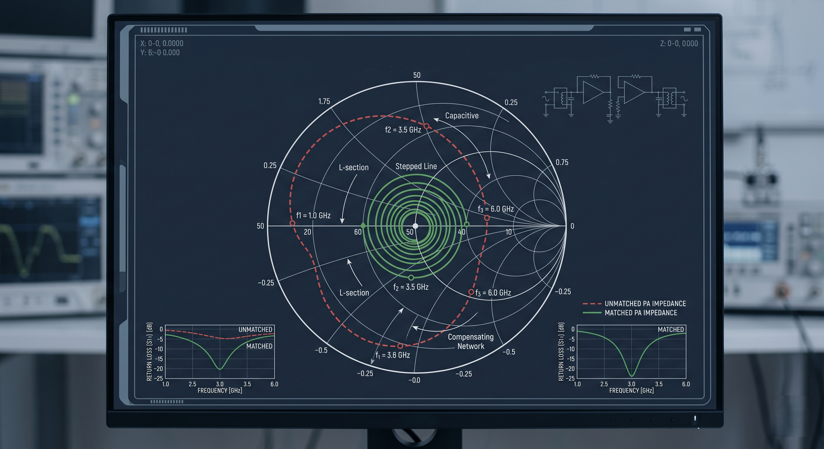
Handling impedance matching in broadband linear RF amplifiers involves creating a network that provides a consistent, optimal load to the transistor across the entire frequency range. This maximizes power transfer, gain flatness4, and linearity while minimizing signal reflections5.
I remember a project where we battled this exact issue. The client needed an amplifier for a new satellite communication system, but we couldn't get the gain flat enough across the required band. It was a classic, frustrating case of impedance matching challenges. This experience taught me just how critical a good match is for overall performance. Let's explore why this is so tricky and how we, as engineers, solve it.
What are the traditional methods for broadband matching?
Are your old matching techniques failing on new wideband designs? Traditional methods are simple but often can't handle today's extreme bandwidths. This leads to compromised performance and lengthy, expensive redesigns.
Traditional methods include multi-section quarter-wave transformers6 and lumped-element (L-C) networks. These techniques work by cascading multiple simple matching stages, each optimized for a part of the frequency band, to approximate a broadband match.
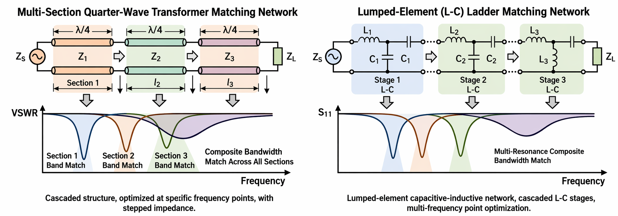
In my early days as an RF engineer, these traditional methods were my entire toolkit. We would spend hours, sometimes days, carefully calculating the values for each section. The goal was to transform the device's impedance to the system's standard 50 ohms. For moderate bandwidths, this works reasonably well. You can add more sections to cover a wider frequency range, but it's a game of trade-offs. Each additional component adds insertion loss, complexity, and another potential point of failure. I've spent countless hours at the workbench, physically tuning tiny capacitors and inductors, watching the network analyzer. You adjust one component to fix the match at the low end of the band, and suddenly the high end is out of whack. It requires a lot of experience and patience to find that delicate balance.
Comparing Traditional Matching Techniques
| Technique | Pros | Cons | Best For |
|---|---|---|---|
| Quarter-Wave Transformers | Simple theory, good for moderate bandwidths | Bulky at low frequencies, step-like response | Fixed-frequency or moderate-band applications |
| Lumped L-C Networks | Compact, flexible design | Parasitics at high frequencies, can be lossy | HF to microwave frequencies, where size matters |
| Tapered Lines | Very broadband, smooth transition | Long physical length, complex to fabricate | Ultra-wideband (UWB) systems where space is not a constraint |
Why is achieving high linearity so difficult with wide bandwidths?
Is your amplifier's linearity dropping as you push for more bandwidth? This common problem causes signal distortion. It happens because the transistor's ideal load impedance for linearity changes with power and frequency.
Achieving high linearity7 is difficult because the optimal load impedance for linearity is not a single point. It varies with frequency and input power. A broadband matching network must present a compromise impedance across the band, which often sacrifices peak linearity.
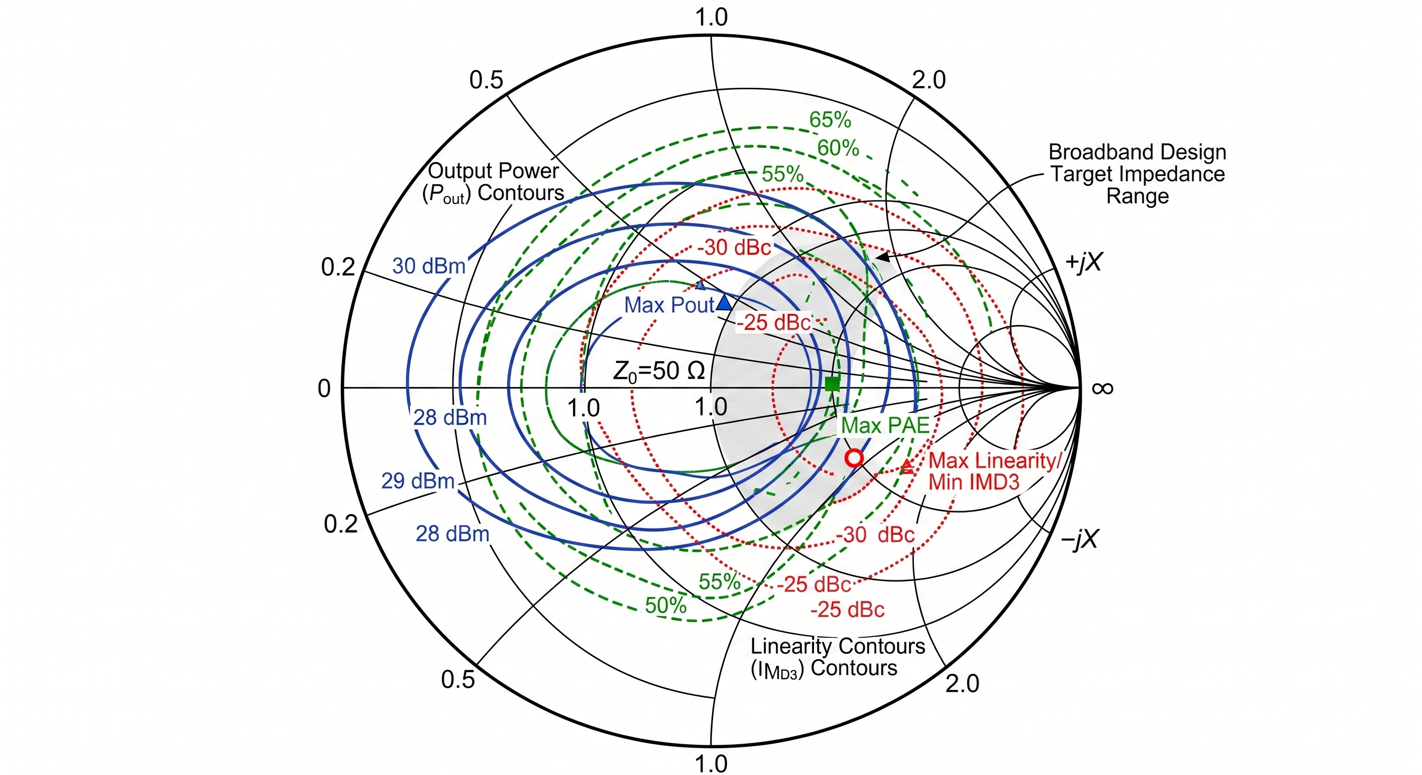
This is one of the biggest headaches in modern amplifier design. We use a technique called "load-pull8" to characterize a transistor. We test the device with hundreds of different load impedances at a specific frequency to find the "sweet spot" for best linearity, or best efficiency, or best output power. The problem is, these sweet spots are in different places. Worse, they move as the frequency changes. I was working on a 2-18 GHz linear amplifier, a core product type for us at Safari Microwave. The load-pull8 data showed the ideal linearity point at 2 GHz was on one side of the Smith chart, while the ideal point at 18 GHz was on the complete opposite side. Our job was to design a matching network that traced a path between those points, staying "close enough" to deliver good, consistent linearity across the entire band. It's the art of the engineered compromise.
The Core Challenges to Linearity
- Frequency-Dependent Behavior: Transistors are not ideal black boxes. Their internal characteristics, like capacitance, change with frequency. This alters the load impedance they need to see to perform optimally.
- Varying Power Levels: The optimal load for a small signal is different from the optimal load for a large signal. This is the very definition of non-linearity. The matching network is fixed, but the signal it's handling is dynamic.
- Memory Effects: This is a sneaky one. A transistor's behavior can be affected by the signals that came just before it. In wideband systems9 with complex signals, this is a huge problem. Our matching network needs to control the impedance not just at the main frequency, but at its harmonics too, to minimize these effects.
How is AI changing the way we design matching networks?
Are you stuck spending weeks manually optimizing matching networks? This old process is slow and often misses the best solution. AI can now automate this, finding better designs in a fraction of the time.
AI and machine learning algorithms are revolutionizing matching network design. By processing transistor S-parameters10 and non-linear models, AI can explore millions of potential network topologies automatically, finding unconventional solutions that maximize bandwidth and linearity.
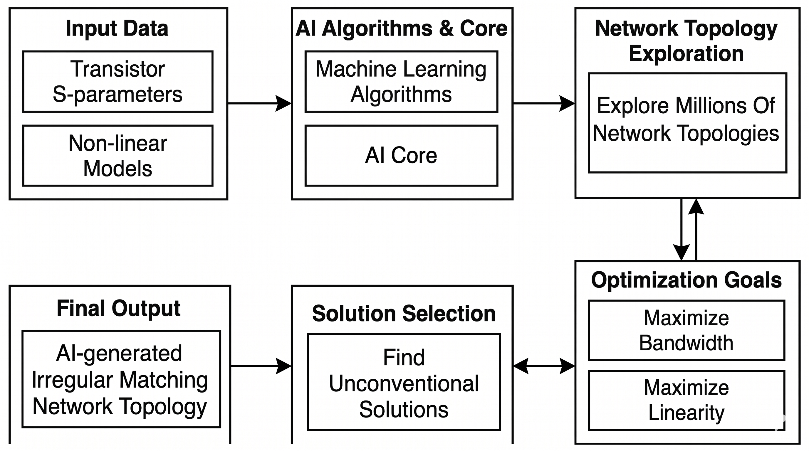
As we push into the 6G3 era, the demands for both massive bandwidth and extreme linearity are becoming impossible to meet with traditional methods alone. This is where AI comes in. I was skeptical at first, like many engineers with 30 years of experience. But I saw it in action. We fed an AI algorithm the non-linear model of a new GaN transistor. We gave it our goals: a flat gain and linear performance from 6 to 18 GHz, a challenge we face regularly when developing our ultra-wideband11 PAs The AI worked for a few hours and produced a network topology. It looked strange, with components in places I would never have thought to put them. It was not a standard textbook design. But when we simulated it, the performance was incredible. It achieved a flatter group delay and better linearity across the band than what would have taken me weeks of manual, iterative tuning. This is the future. It provides a brand new, powerful starting point that we can then refine with our engineering judgment.
AI's Impact on Amplifier Design
- Speed: It reduces design time from weeks to hours. This allows us to respond to customer needs, like those from our client Mark Chen, much faster.
- Performance: It finds novel, non-intuitive solutions that outperform human-designed networks, especially for the "High Power, Ultra-Wideband" amplifiers we specialize in.
- Complexity Management: It can optimize for multiple goals at once. It balances gain, bandwidth, linearity, and efficiency in a way that is nearly impossible for a human to do manually.
- New Possibilities: It empowers engineers. We are not being replaced; we are being given a more powerful tool to solve the next generation of RF challenges.
Conclusion
Broadband impedance matching is a complex trade-off, but new AI-driven design methods are helping us create the high-performance, ultra-wideband linear amplifiers needed for the future of communication.
Understanding impedance mismatch can help you improve amplifier performance and efficiency. ↩
Stay updated on the latest bandwidth demands shaping the future of communication technology. ↩
Understand the unique challenges posed by 6G technology in RF design and engineering. ↩
Learn techniques to ensure gain flatness, crucial for high-performance RF amplifiers. ↩
Discover the causes of signal reflections and how to minimize them for better signal integrity. ↩
Gain insights into quarter-wave transformers and their role in RF matching networks. ↩
Learn why achieving high linearity is crucial for maintaining signal integrity in RF systems. ↩
Learn about load-pull testing and its importance in optimizing RF amplifier performance. ↩
Learn how complex signals impact RF amplifier performance and design considerations. ↩
Discover the significance of S-parameters in characterizing transistor performance. ↩
Explore the applications and benefits of ultra-wideband power amplifiers in modern technology. ↩
