
A BUC loses its lock, and your entire Satcom link goes down. You've checked the reference signal, but the problem persists. The real cause might be hiding in plain sight.
PLL unlock issues in BUCs are often caused by excessive power supply ripple, not just an unstable reference signal.1 To fix this, focus on your BUC's power circuit. Proper filtering, separate grounds, and linear regulators are essential for a stable lock and reliable performance.

I remember a case a few years ago that perfectly illustrates this. We had a client with a BUC that kept losing its lock intermittently. They were convinced it was a faulty reference source. After hours of debugging, we found the real culprit. This experience taught me a valuable lesson. Let's dig into why the power supply is so critical.
Why Does Power Supply Ripple Wreak Havoc on a PLL?
Your BUC's PLL seems sensitive, dropping its lock unexpectedly. You suspect noise, but where is it coming from? The power supply might be injecting noise directly into your critical circuits.
Power supply ripple introduces unwanted noise and voltage variations. A PLL's Voltage-Controlled Oscillator (VCO) is highly sensitive to these fluctuations.2 This noise can push the VCO's control voltage outside its locking range, causing the entire Phase-Locked Loop to unlock and fail.
Let's break this down. The PLL's job is to generate a stable high-frequency signal by locking it to a lower-frequency reference. The core component is the VCO. The VCO's output frequency is directly controlled by a DC voltage. Any small change in this control voltage changes the output frequency. When your power supply has high ripple, it's like adding an unwanted AC signal on top of your clean DC power. This noise gets into the sensitive control voltage line of the VCO. The PLL's loop filter tries to correct this, but if the ripple is too large or at a specific frequency, it can overwhelm the system. The VCO frequency then jitters too much, and the phase detector can't maintain a lock. This is why a "clean" power source is not a luxury; it's a necessity for stable BUC operation. Imagine trying to stand still on a shaking platform; that's what the VCO is trying to do with a noisy power supply. At Safari Microwave, when we design our high-power amplifiers, like our 3000W saturated power amplifier, we pay extreme attention to this. A stable PLL is fundamental to achieving the Low-Spurious performance our customers demand. It's a non-negotiable part of our design philosophy.
Key Components Affected by Power Ripple
| Komponenta | How Ripple Affects It | Consequence |
|---|---|---|
| VCO | Directly modulates the control voltage, causing frequency jitter. | Loss of frequency stability. |
| Charge Pump | Introduces errors in the current pulses, affecting lock time.3 | Slower locking or failure to lock. |
| Reference Input | Can degrade the signal-to-noise ratio of the reference signal. | PLL sees a noisy reference. |
| Digital Logic | Can cause logic level errors if ripple is severe.4 | Unpredictable PLL behavior. |
How Can You Effectively Diagnose Power Supply Issues in Your BUC?
You suspect the power supply is the problem, but how can you be sure? Guessing is expensive and time-consuming. You need a clear, methodical way to test and confirm the issue.
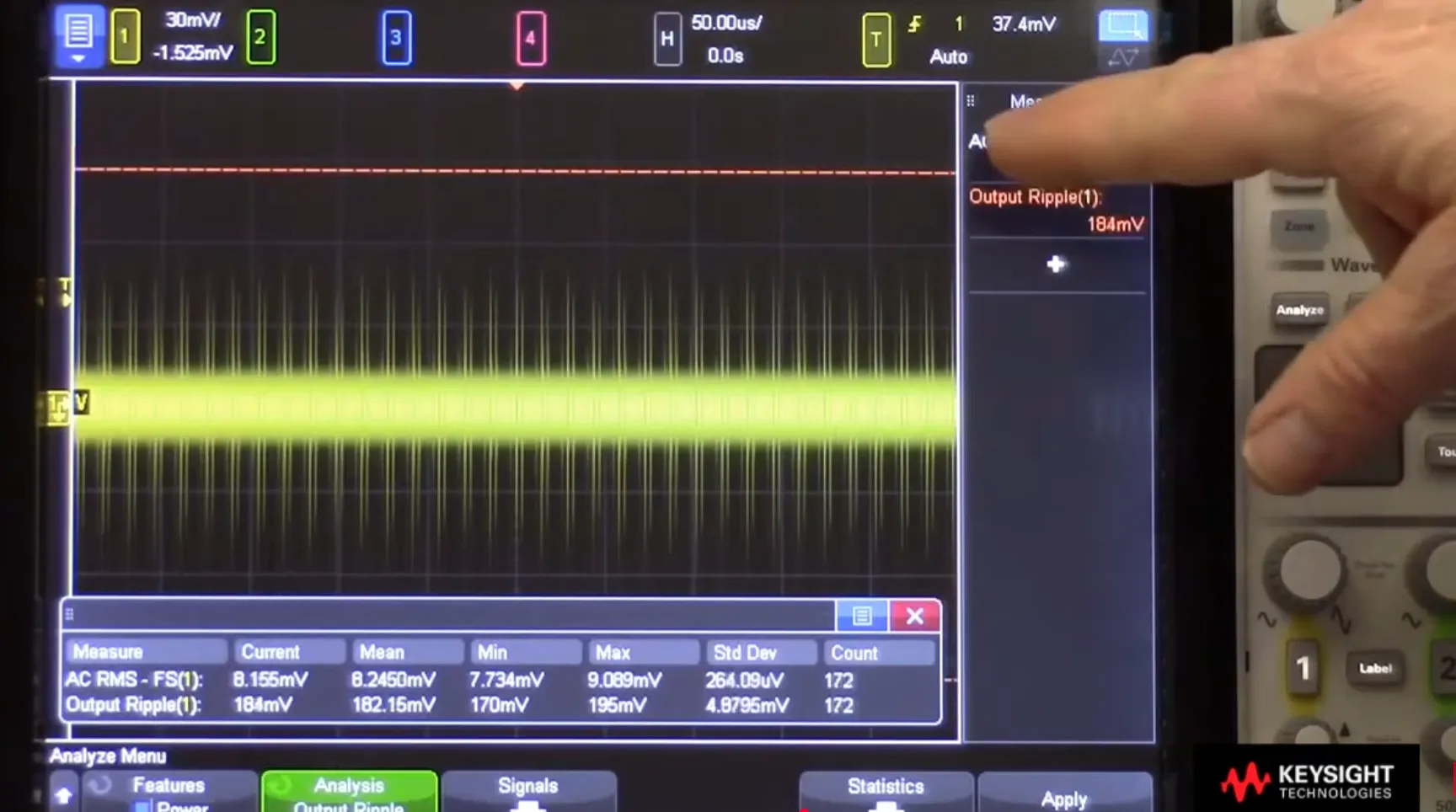
To diagnose power supply issues, use an oscilloscope to measure the ripple on the BUC's DC input lines. Check the ripple under both no-load and full-load conditions.5 Compare this measurement against the BUC's specified power supply ripple tolerance to confirm if it's the root cause.
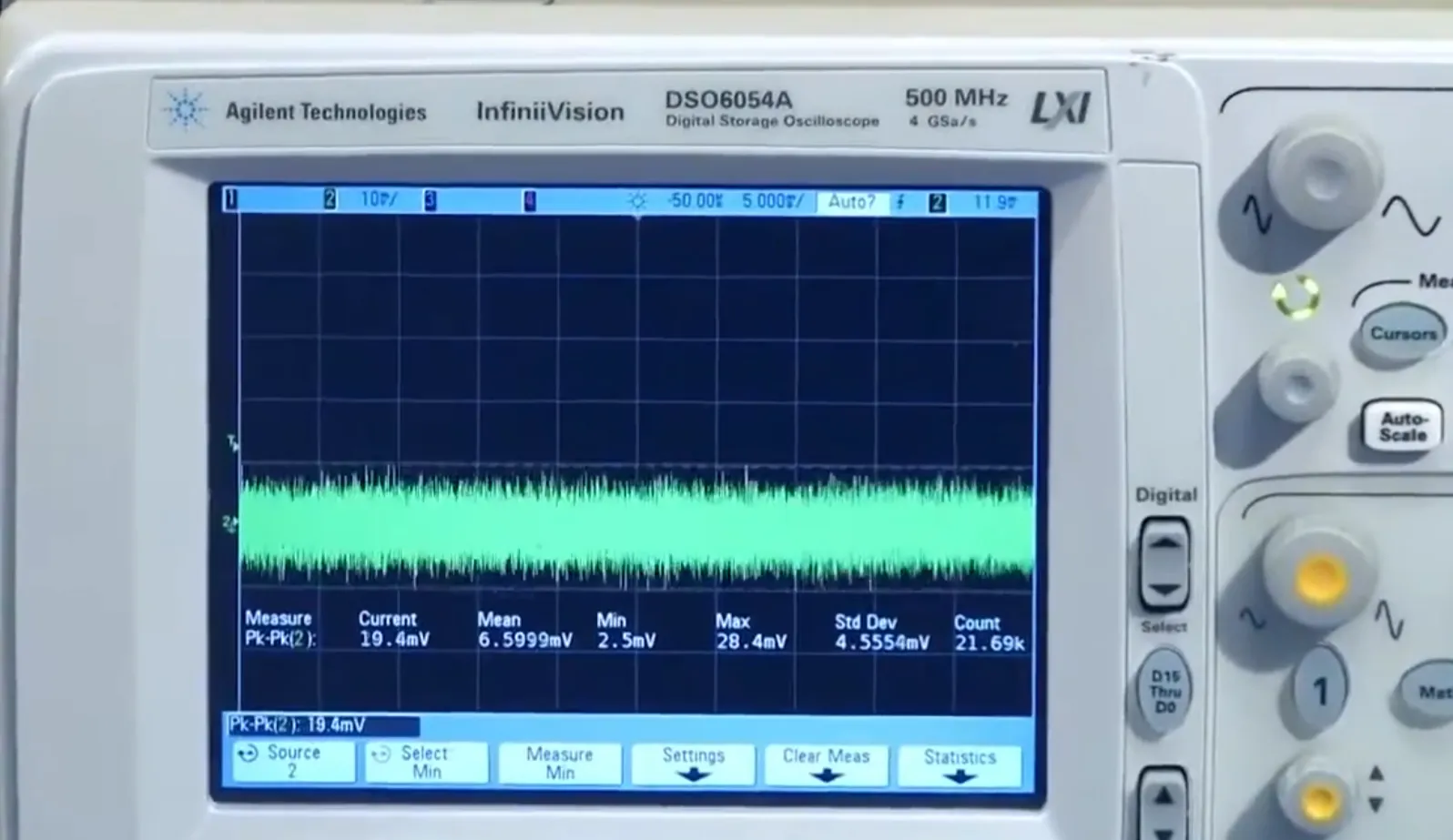
Diagnosing this isn't black magic; it's about careful measurement. First, get a good oscilloscope with enough bandwidth. Connect your BUC to its power source and let it operate normally to simulate a real-world load. Now, probe the DC power input pins on the BUC itself. It's important to measure as close to the BUC as possible. Set your oscilloscope to AC coupling to remove the large DC offset, allowing you to see the small AC ripple riding on the DC voltage. Measure the peak-to-peak voltage of this ripple. A good power supply might have ripple under 50mV, while a noisy one could be hundreds of millivolts.6 I often see engineers make the mistake of measuring the power supply output with no load attached. This is misleading, as the BUC itself can draw current in a way that creates more noise. Always test under realistic operating conditions. Another useful tool is a spectrum analyzer with a near-field probe. You can use it to 'sniff' around the power supply circuitry on the board to identify sources of RF noise that might be coupling onto the power lines. This can help pinpoint noisy components, like a switching regulator, that might be the root cause. It’s how you find those tough, intermittent problems.
Quick Diagnostic Checklist
| cURL Too many subrequests by single Worker invocation. To configure this limit, refer to https://developers.cloudflare.com/workers/wrangler/configuration/#limits | cURL Too many subrequests by single Worker invocation. To configure this limit, refer to https://developers.cloudflare.com/workers/wrangler/configuration/#limits | What to Look For |
|---|---|---|
| 1. Visual Check | Inspect power supply capacitors for bulging or leaks. | cURL Too many subrequests by single Worker invocation. To configure this limit, refer to https://developers.cloudflare.com/workers/wrangler/configuration/#limits. |
| cURL Too many subrequests by single Worker invocation. To configure this limit, refer to https://developers.cloudflare.com/workers/wrangler/configuration/#limits | cURL Too many subrequests by single Worker invocation. To configure this limit, refer to https://developers.cloudflare.com/workers/wrangler/configuration/#limits. | cURL Too many subrequests by single Worker invocation. To configure this limit, refer to https://developers.cloudflare.com/workers/wrangler/configuration/#limits. |
| cURL Too many subrequests by single Worker invocation. To configure this limit, refer to https://developers.cloudflare.com/workers/wrangler/configuration/#limits | cURL Too many subrequests by single Worker invocation. To configure this limit, refer to https://developers.cloudflare.com/workers/wrangler/configuration/#limits. | cURL Too many subrequests by single Worker invocation. To configure this limit, refer to https://developers.cloudflare.com/workers/wrangler/configuration/#limits. |
| cURL Too many subrequests by single Worker invocation. To configure this limit, refer to https://developers.cloudflare.com/workers/wrangler/configuration/#limits | cURL Too many subrequests by single Worker invocation. To configure this limit, refer to https://developers.cloudflare.com/workers/wrangler/configuration/#limits. | cURL Too many subrequests by single Worker invocation. To configure this limit, refer to https://developers.cloudflare.com/workers/wrangler/configuration/#limits |
What Are the Best Design Practices to Prevent PLL Unlock?
cURL Too many subrequests by single Worker invocation. To configure this limit, refer to https://developers.cloudflare.com/workers/wrangler/configuration/#limits
cURL Too many subrequests by single Worker invocation. To configure this limit, refer to https://developers.cloudflare.com/workers/wrangler/configuration/#limits, cURL Too many subrequests by single Worker invocation. To configure this limit, refer to https://developers.cloudflare.com/workers/wrangler/configuration/#limits.7
cURL Too many subrequests by single Worker invocation. To configure this limit, refer to https://developers.cloudflare.com/workers/wrangler/configuration/#limits.
cURL Too many subrequests by single Worker invocation. To configure this limit, refer to https://developers.cloudflare.com/workers/wrangler/configuration/#limits
| Technique | cURL Too many subrequests by single Worker invocation. To configure this limit, refer to https://developers.cloudflare.com/workers/wrangler/configuration/#limits | Why It Works |
|---|---|---|
| cURL Too many subrequests by single Worker invocation. To configure this limit, refer to https://developers.cloudflare.com/workers/wrangler/configuration/#limits | cURL Too many subrequests by single Worker invocation. To configure this limit, refer to https://developers.cloudflare.com/workers/wrangler/configuration/#limits. | cURL Too many subrequests by single Worker invocation. To configure this limit, refer to https://developers.cloudflare.com/workers/wrangler/configuration/#limits.8 |
| cURL Too many subrequests by single Worker invocation. To configure this limit, refer to https://developers.cloudflare.com/workers/wrangler/configuration/#limits | cURL Too many subrequests by single Worker invocation. To configure this limit, refer to https://developers.cloudflare.com/workers/wrangler/configuration/#limits.9 | cURL Too many subrequests by single Worker invocation. To configure this limit, refer to https://developers.cloudflare.com/workers/wrangler/configuration/#limits. |
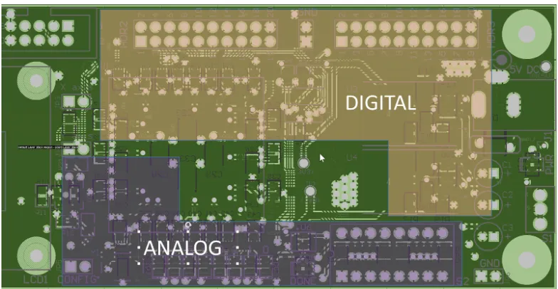
| cURL Too many subrequests by single Worker invocation. To configure this limit, refer to https://developers.cloudflare.com/workers/wrangler/configuration/#limits | Keep analog and digital grounds separate on the PCB. | Prevents digital noise from coupling into sensitive analog circuits. |
| Ferrite Beads | Place a ferrite bead in series on the power supply line. | Acts as a filter to block high-frequency noise.10 |
Zaključak
Solving BUC PLL unlock issues often means looking beyond the reference signal. A clean, well-filtered power supply is the foundation of a reliable system. Focus on power integrity first.
"Reduction of noise induced by power supply lines using phase ...", https://pubmed.ncbi.nlm.nih.gov/36461473/. Research and application notes on RF circuit design confirm that power supply noise, or ripple, is a primary cause of instability and lock failure in Phase-Locked Loops (PLLs) by injecting noise into sensitive control nodes. Evidence role: general_support; source type: paper. Supports: That excessive power supply ripple is a known and significant cause of Phase-Locked Loop (PLL) unlock failures in RF systems.. ↩
"The Basics of Voltage Controlled Oscillators (VCOs) and ... - DigiKey", https://www.digikey.com/en/articles/the-basics-of-voltage-controlled-oscillators-vcos. Educational materials and component datasheets on VCOs explain their inherent sensitivity to power supply variations, a phenomenon known as 'pushing,' where changes in supply voltage directly affect the output frequency. Evidence role: mechanism; source type: education. Supports: That VCOs are inherently sensitive to variations on their power supply lines, a characteristic often quantified as 'VCO pushing' or 'power supply sensitivity.'. ↩
"A Low Mismatch Current Charge Pump Applied to Phase-Locked ...", https://pmc.ncbi.nlm.nih.gov/articles/PMC11278738/. Studies on PLL design demonstrate that power supply noise can affect the charge pump by creating mismatches or jitter in the current pulses, which in turn degrades the loop's dynamic performance, including increasing the time required to achieve lock. Evidence role: mechanism; source type: paper. Supports: That noise on the power supply rail of a charge pump can introduce timing jitter or amplitude errors in the current pulses, which can degrade PLL performance metrics like lock time and phase noise.. ↩
"Noise margins in digital integrated circuits - NASA ADS", https://ui.adsabs.harvard.edu/abs/1964IEEEP..52.1565L/abstract. Fundamentals of digital electronics establish that for logic gates to operate reliably, their supply voltage must remain within specified tolerances. Severe power supply ripple can violate these voltage margins, causing intermittent logic errors. Evidence role: mechanism; source type: education. Supports: That significant voltage drops or spikes on the power supply rail can cause the voltage to fall below the minimum high-level input voltage (VIH) or rise above the maximum low-level input voltage (VIL) of digital logic gates, leading to incorrect state interpretation.. ↩
"How to Measure Power Supply Ripple on an Oscilloscope", https://resources.pcb.cadence.com/blog/how-to-measure-power-supply-ripple-on-an-oscilloscope. Test and measurement guides from electronics manufacturers emphasize the importance of measuring power supply ripple under full-load conditions, as the dynamic current draw of the device under test often reveals worst-case ripple that is not present in a no-load state. Evidence role: general_support; source type: other. Supports: That a comprehensive power supply ripple measurement involves testing under various load conditions, as the load itself can induce or exacerbate ripple and noise.. Scope note: The source would provide a general testing methodology, not one specific to BUCs, but the principle is directly applicable. ↩
"Ripple (electrical) - Wikipedia", https://en.wikipedia.org/wiki/Ripple_(electrical). Power supply design literature for sensitive analog circuits often specifies ripple targets in the tens of millivolts (e.g., <50 mVp-p), while noting that unoptimized switching supplies can easily produce ripple of several hundred millivolts. Evidence role: statistic; source type: paper. Supports: That for sensitive analog and RF applications, power supply ripple is often specified to be well below 50mV peak-to-peak, while less regulated supplies can exhibit ripple in the hundreds of millivolts.. Scope note: The exact values can vary significantly depending on the specific application, voltage rail, and circuit sensitivity. ↩
"What Are the Basic Guidelines for Layout Design of Mixed-Signal ...", https://www.analog.com/en/resources/analog-dialogue/articles/what-are-the-basic-guidelines-for-layout-design-of-mixed-signal-pcbs.html. Standard PCB design guidelines for mixed-signal systems advocate for the separation of analog and digital ground planes, connecting them at a single point (a 'star' ground), to prevent digital switching noise from contaminating sensitive analog circuits. Evidence role: general_support; source type: education. Supports: That separating analog and digital ground planes on a PCB is a standard and critical technique to prevent noisy return currents from the digital section from flowing through and corrupting the sensitive analog section.. ↩
"Power supply rejection ratio", https://en.wikipedia.org/wiki/Power_supply_rejection_ratio. The Power Supply Rejection Ratio (PSRR) of a linear regulator quantifies its ability to block unwanted AC components (noise and ripple) from its input, preventing them from appearing on its output. LDOs selected for analog applications typically feature high PSRR across a wide frequency range. Evidence role: definition; source type: encyclopedia. Supports: That Power Supply Rejection Ratio (PSRR) is a measure of how well a circuit, such as an LDO, rejects ripple from its input supply, and that LDOs are specifically designed to have a high PSRR.. ↩
"[PDF] Design and Implementation of Active Decoupling Capacitor Circuits ...", http://people.ece.umn.edu/groups/VLSIresearch/papers/2009/TVLSI09_ActiveDecap.pdf. Best practices for power delivery network (PDN) design involve placing a parallel combination of decoupling capacitors with different values close to the IC power pins. This technique ensures a low-impedance supply path over a broad frequency range, with smaller capacitors targeting high-frequency noise and larger ones handling low-frequency demands. Evidence role: mechanism; source type: paper. Supports: That using multiple capacitors of different values (e.g., a large electrolytic for low frequencies and small ceramics for high frequencies) placed close to an IC's power pins creates a low-impedance path to ground across a wide frequency spectrum.. ↩
"Ferrite bead - Wikipedia", https://en.wikipedia.org/wiki/Ferrite_bead. Component datasheets and electronics engineering resources explain that a ferrite bead functions as a frequency-dependent resistor, presenting a high impedance to high-frequency noise on a power line while allowing DC current to pass with minimal opposition. Evidence role: definition; source type: other. Supports: That ferrite beads are passive electronic components that act as high-frequency filters, exhibiting low impedance at DC and low frequencies but high impedance at high frequencies, thereby suppressing noise.. ↩
