
Designing a multiband SSPA with a perfectly flat gain curve feels like an impossible task. The physics just seems to be working against you. But it is achievable.
To design a multiband Solid State Power Amplifier (SSPA) with flat gain, you must combine three techniques1. First, use a negative feedback circuit for stability. Second, add an R-L-C input matching network to flatten the gain. Third, use wideband load-pull to control harmonics and maintain efficiency.

I've been designing RF components for over a decade, and this challenge comes up on almost every wideband project. The temptation is to focus on just one area, like output power, and hope for the best. But that never works. A great wideband amplifier isn't about one single achievement; it's about balancing multiple competing factors. The good news is that there's a proven method. By breaking the problem down into three specific areas—gain stability, gain shaping, and harmonic control—you can build an amplifier that performs consistently across its entire frequency range. Let’s walk through how we do it.
How does negative feedback stabilize gain in a distributed amplifier?
You've built a distributed amplifier, but the gain is all over the place. It seems to change with temperature, frequency, and even on different days. This makes it unreliable.
Negative feedback is the key to taming this instability. By feeding a small, inverted portion of the output signal back to the input, you sacrifice a little gain to achieve a much more predictable and flat response across the entire band.
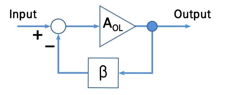
In my experience, especially with distributed architectures where you're combining power from multiple transistors, inherent gain can be very high but also very unstable. The primary job of negative feedback is to bring order to this chaos. Think of it as a governor on an engine. It keeps things from running wild. We intentionally reduce the overall gain, which might sound counterintuitive. But in return, we get a system that is far less sensitive to variations in individual components or operating conditions. I remember a specific project where the prototype's gain swung by 4 dB across the band. After implementing a simple resistive feedback loop, that variation dropped to less than 1 dB. The amplifier became a reliable, predictable building block. This stability also helps improve the input and output return loss, making the SSPA easier to integrate into a larger system.
| Parameter | Without Negative Feedback | With Negative Feedback |
|---|---|---|
| Gain Variation | High (e.g., >3 dB) | Low (e.g., <1 dB) |
| Stability | Poor, sensitive to changes | Excellent, very robust |
| Return Loss | Poor | Good |
Why is an R-L-C network crucial for input matching?
Even with feedback, your gain probably still droops at high frequencies. Most transistors naturally have more gain at lower frequencies. This imbalance ruins your wideband performance.
An R-L-C input matching network acts as a gain equalizer2. It's designed to introduce more loss at lower frequencies3, bringing the gain down to match the naturally lower gain at higher frequencies. This is how you achieve a flat response.
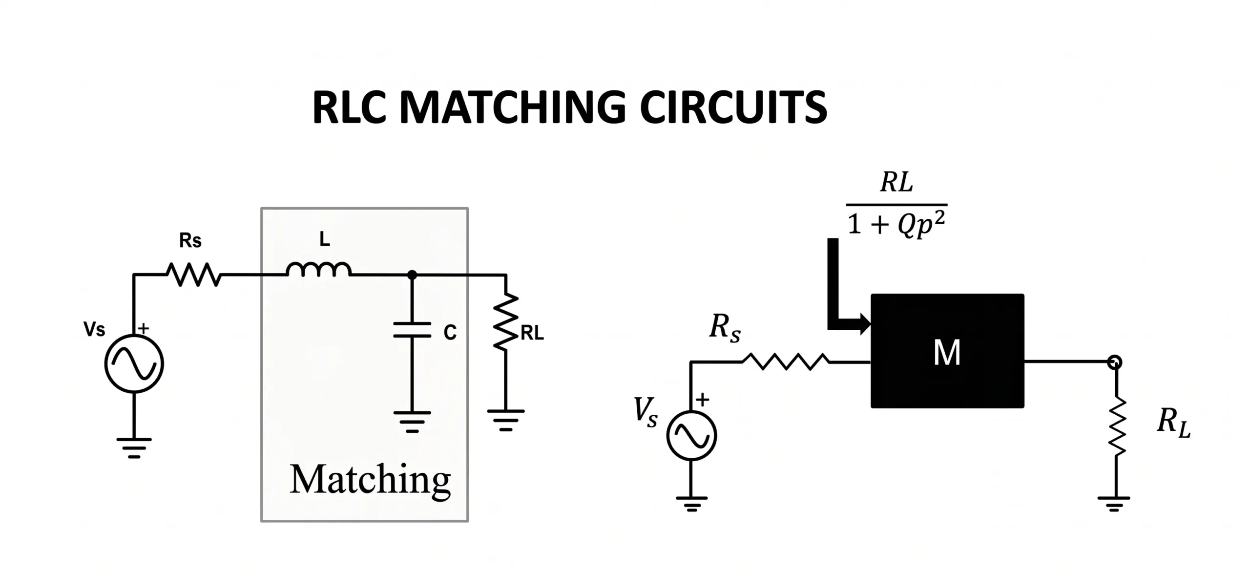
This is a step that many designers overlook. They spend all their time trying to boost the high-frequency gain, which is incredibly difficult and often compromises other aspects of the design. The smarter approach is to gently reduce the low-frequency gain. This is where the R-L-C network comes in. The resistor (R) is what creates the loss, and the inductor (L) and capacitor (C) make that loss frequency-dependent. At low frequencies, the network is designed to have a lower impedance, causing more of the input signal to be attenuated. As the frequency increases, the network's impedance rises, and less signal is lost. For a recent 3000-watt SSPA we developed at Safari Microwave, this was the exact technique we used. The raw amplifier had a 5 dB downward tilt from 2 GHz to 6 GHz. By carefully tuning the R-L-C values, we flattened it to within 0.8 dB, creating a truly ultra-wideband product.
| Frequency | Gain without RLC Network | Gain with RLC Network |
|---|---|---|
| Low Band | 20 dB | 16 dB |
| Mid Band | 18 dB | 15.8 dB |
| High Band | 15 dB | 15.2 dB |
What is the role of wideband load-pull in harmonic suppression?
Your gain is finally flat, but your Power Added Efficiency (PAE) is terrible. Looking closer, you see that harmonics are running wild, distorting your signal and wasting precious DC power.
Wideband load-pull with harmonic termination controls these unwanted harmonics4. By presenting a specific, engineered impedance to the fundamental frequency and its harmonics, you can suppress their power, preventing distortion and maximizing PAE5.
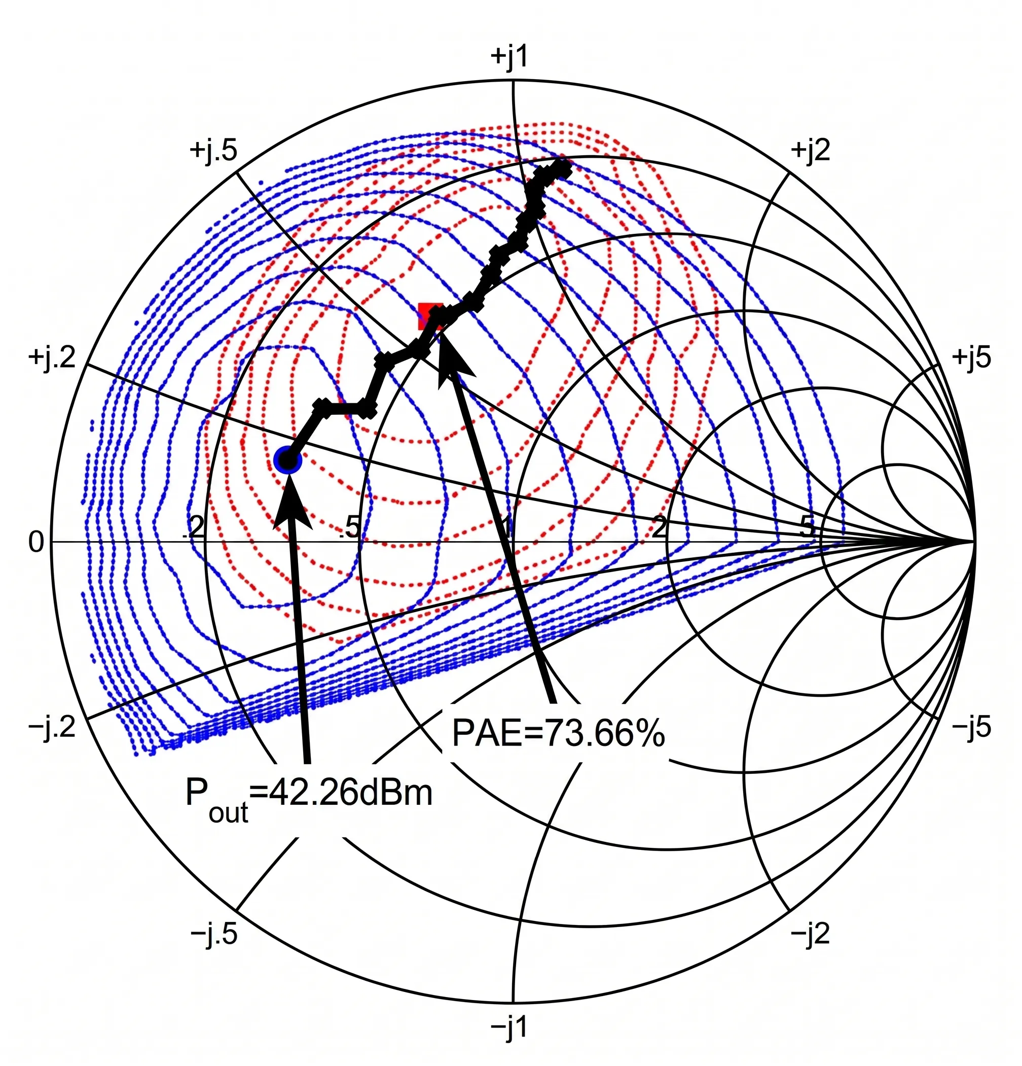
This is the most advanced part of the design, but it’s absolutely critical for high-performance SSPAs. Harmonics are an unavoidable byproduct of amplification. In a wideband amplifier, a 2nd or 3rd harmonic from a low-frequency signal can actually fall inside your operating band6 at a higher frequency. This creates in-band distortion and kills your signal integrity. Load-pull is the process of finding the perfect output impedance (load) for the transistor. With "wideband load-pull," we don't just find one perfect impedance. We use advanced models to find the ideal impedance for the fundamental signal while also presenting a specific impedance (often a short or open circuit) to the 2nd and 3rd harmonics. This effectively traps and cancels the harmonic energy at the source. At Safari Microwave, our work on amplifiers up to 110 GHz relies heavily on this. Neglecting harmonic termination can easily cut your PAE in half7. It is the difference between a mediocre amplifier and a premium-efficiency, low-spurious one.
| Design Goal | Standard Load-Pull | With Harmonic Termination |
|---|---|---|
| PAE | 45% | 65% |
| 2nd Harmonic | -25 dBc | -45 dBc |
| Signal Integrity | Moderate | Excellent |
Conclusion
A high-performance multiband SSPA requires a three-part strategy: use negative feedback for stability, an RLC input network for gain flattening, and wideband load-pull for harmonic control and efficiency.
"Systemizing the Design of Broadband Class-A RF Power Amplifiers", https://www.academia.edu/30184892/Systemizing_the_Design_of_Broadband_Class_A_RF_Power_Amplifiers. Scholarly articles on RF amplifier design often describe a multi-faceted approach for achieving flat gain and high efficiency over wide bandwidths, incorporating methods for stabilization, gain equalization, and output matching with harmonic considerations. Evidence role: general_support; source type: paper. Supports: The claim that achieving flat gain in wideband SSPAs requires a combination of techniques including feedback for stability, gain equalization networks, and harmonic control.. ↩
"Impedance matching - Wikipedia", https://en.wikipedia.org/wiki/Impedance_matching. Technical papers on broadband amplifier design document the use of passive RLC networks as gain equalizers, which are designed to introduce a frequency-dependent attenuation that compensates for the natural gain roll-off of the active device. Evidence role: definition; source type: paper. Supports: The claim that R-L-C networks are used as gain equalizers in amplifier design.. ↩
"RLC circuit - Wikipedia", https://en.wikipedia.org/wiki/RLC_circuit. Design methodologies for gain-flattened amplifiers often employ reactive-resistive networks that provide higher attenuation at lower frequencies, where the transistor's intrinsic gain is highest, to achieve a level gain response across the desired band. Evidence role: mechanism; source type: paper. Supports: The claim that gain equalizers for RF amplifiers often work by attenuating lower frequencies.. ↩
"Study of Power Amplifier Harmonic Output Termination for two ...", https://ieeexplore.ieee.org/document/9253908/. Research in high-efficiency power amplifiers demonstrates that wideband load-pull systems are used to characterize and design for optimal performance by not only presenting the ideal impedance at the fundamental frequency but also specific terminating impedances at harmonic frequencies. Evidence role: definition; source type: research. Supports: The claim that wideband load-pull with harmonic termination is a method for controlling harmonics.. ↩
"High-efficiency 5-watt power amplifier with harmonic tuning - ADS", https://ui.adsabs.harvard.edu/abs/1988mwsy.conf..152K/abstract. Studies on power amplifier efficiency show that by controlling the load impedances at the second and third harmonics (e.g., presenting a short or open circuit), the voltage and current waveforms at the transistor's output can be shaped to minimize their overlap, thus reducing dissipated power and maximizing PAE. Evidence role: mechanism; source type: paper. Supports: The claim that controlling harmonics through load impedance manipulation can maximize Power Added Efficiency (PAE).. ↩
"Intermodulation noise related to THD in wide-band amplifiers", https://ieeexplore.ieee.org/document/554340/. Technical literature on wideband and multi-octave amplifiers highlights the challenge of in-band harmonics, where, for example, the second harmonic of a signal at the low end of the band falls within the operational frequency range, causing distortion that cannot be filtered externally. Evidence role: general_support; source type: paper. Supports: The claim that harmonics generated at lower frequencies can fall within the passband of a wideband amplifier.. ↩
"Long-Term PAE Results: What Do We Know - PMC", https://pmc.ncbi.nlm.nih.gov/articles/PMC9767787/. Research papers comparing power amplifier designs often report significant improvements in PAE with the implementation of harmonic tuning, with some studies showing increases from around 40-50% to over 70-80%, supporting the claim that neglecting it can result in substantially lower efficiency. Evidence role: statistic; source type: paper. Supports: The claim that harmonic termination can lead to a very large increase in Power Added Efficiency (PAE).. Scope note: The exact percentage of PAE improvement is highly dependent on the transistor technology, frequency, and specific amplifier class being designed. ↩
