
Struggling with spectral regrowth in your BUC? This interference bleeds into adjacent channels, compromising your system. Let's find the true sources beyond just the amplifier.
Spectral regrowth in a Block Upconverter (BUC) is caused by system-level nonlinearities. The main sources are not just the power amplifier, but also the mixer operating nonlinearly, signal envelope compression from high PAPR signals, and poor impedance matching between internal stages1.

I've seen this happen many times in my career. An engineer invests in a top-of-the-line GaN SSPA, expecting a pristine signal output from their BUC. Instead, they are disappointed by significant spectral regrowth. Their first instinct is to blame the amplifier, but the problem is often more complex. A BUC is a small system, and every component in the signal chain plays a role. To truly understand and solve this, we need to look at the entire system. Let's break it down piece by piece.
Why Does a Linear GaN SSPA Still Lead to a Nonlinear BUC?
You chose a high-linearity GaN SSPA for your BUC. But the final output is still nonlinear and disappointing. Let's explore why your investment isn't paying off as expected.
A BUC is a system. While a linear GaN SSPA is crucial, its performance can be undermined by other nonlinear components like the mixer. Also, poor impedance matching between the SSPA and other stages can introduce additional, unexpected nonlinear distortion, degrading overall linearity.
When I talk to clients, this is a common point of frustration. They look at the datasheet for a GaN power amplifier and see excellent linearity specs. They build it into a BUC and the performance falls apart. The key is to stop thinking about the amplifier in isolation and start thinking about the BUC as a complete system.
The System-Level View
A BUC is more than just its SSPA. It's a chain of components: at minimum, a mixer, filters, and the amplifier. Each one has its own performance characteristics. Even a perfectly linear amplifier cannot correct for distortion created earlier in the signal path. If the signal is already distorted when it reaches the amplifier, the amplifier will just make that distorted signal more powerful. This is why our 30 years of engineering experience at Safari Microwave focus heavily on system integration, not just individual component specs.
The Amplifier's Role
Of course, the Solid-State Power Amplifier (SSPA) is a primary source of nonlinearity, especially as it's driven closer to its saturation point. But even the best SSPA has its limits. Our own high-power SSPAs, like our 3000W model, are designed for "High Power, Ultra-Wideband, Low-Spurious, Premium-Efficiency." We design for performance, but understand it must operate within a well-designed system to deliver that performance.
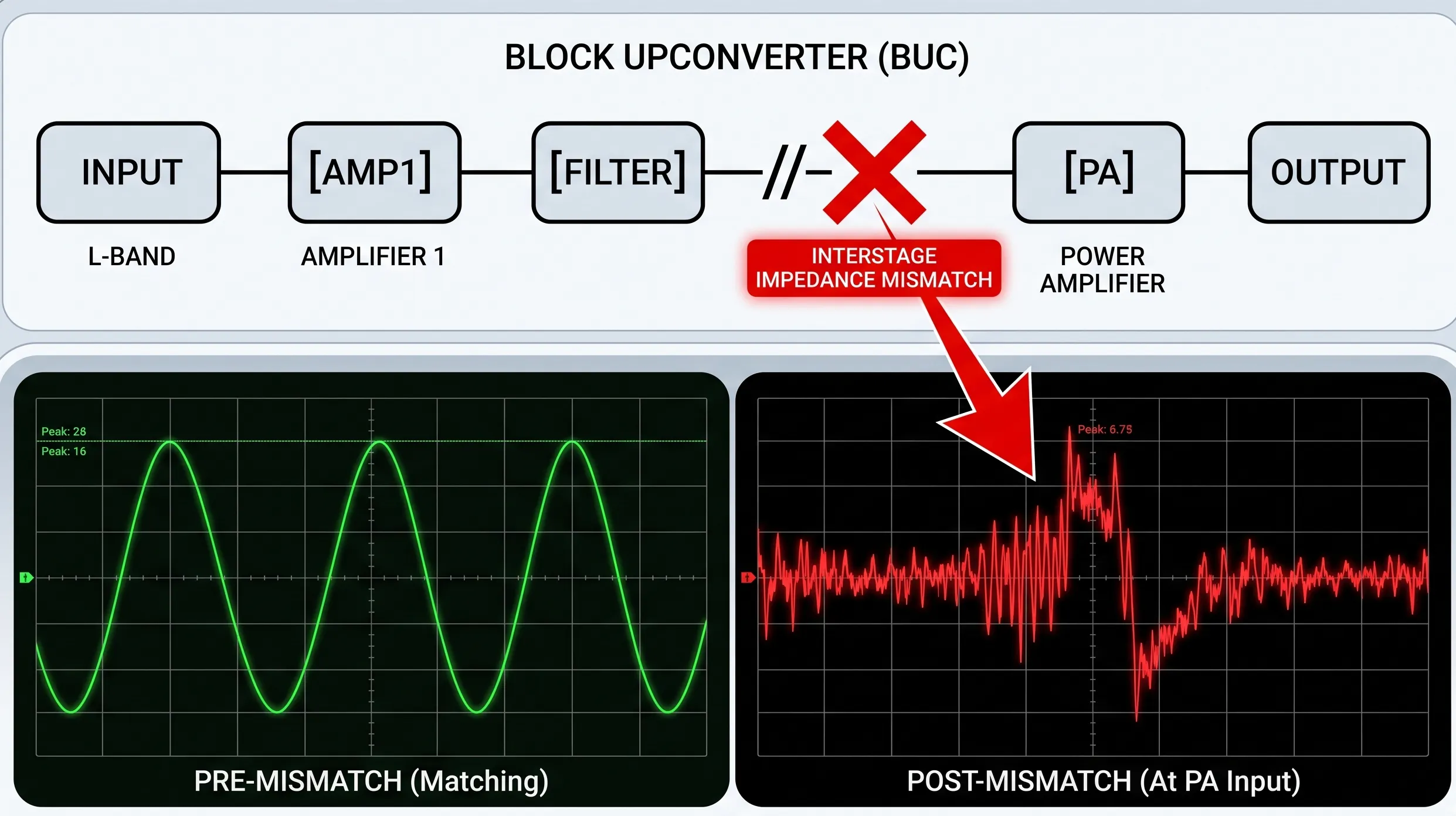
The Impact of Interstage Mismatch
This is the hidden problem I see most often. Every component has an input and output impedance. When these impedances are not perfectly matched, signal power reflects back and forth between stages. These reflections create standing waves, which alter the load impedance the amplifier sees. This can push the amplifier into a nonlinear operating region unexpectedly.
| Mismatch Level (VSWR) | Power Reflected2 | Impact on Linearity |
|---|---|---|
| 1.1:1 (Excellent) | < 0.5% | Minimal, predictable performance. |
| 1.5:1 (Average) | 4% | Moderate, can cause linearity to degrade. |
| 2.0:1 (Poor) | 11% | Significant, unpredictable distortion and regrowth. |
A well-designed BUC from a supplier like us will have carefully matched stages to prevent this exact problem.
How Do Modulated Signals and Mixers Contribute to Nonlinearity?
You've checked your amplifier and matching, but still see regrowth. The problem might be your signal itself or the upconverting mixer. Let's uncover these hidden nonlinearity sources.
Complex modulated signals with a high Peak-to-Average Power Ratio (PAPR) can push components into saturation, causing envelope compression and distortion. The mixer, another active device, also has its own nonlinear characteristics and can be a significant source of intermodulation products if not driven correctly.
The components in your BUC don't just process a simple, constant tone. They have to handle modern, complex communication signals. The nature of that signal, and the components that come before the main power amplifier, are critical sources of nonlinearity.
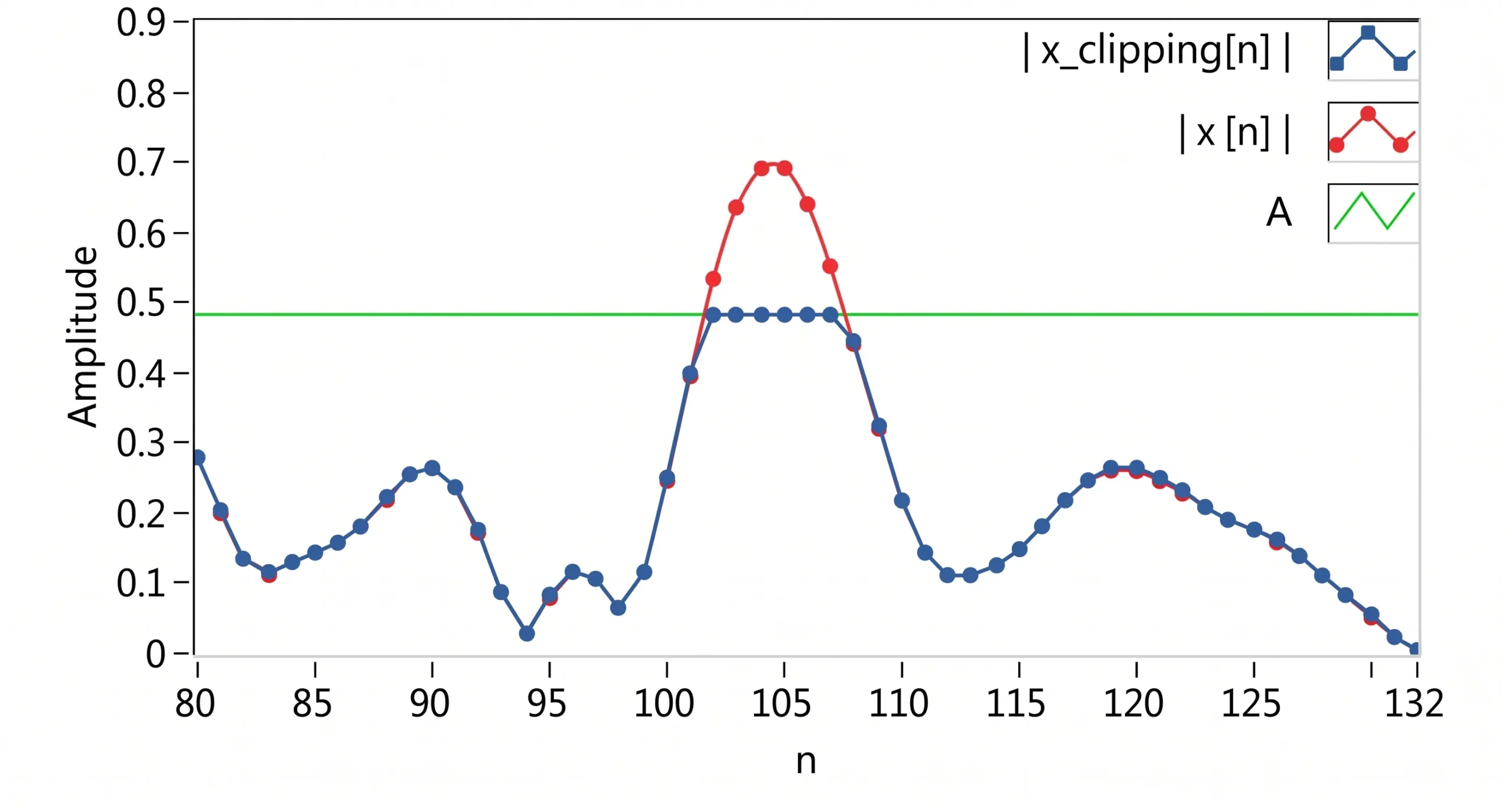
Signal Envelope Compression
Modern modulation schemes like QAM or OFDM are very efficient, but they create signals with a high Peak-to-Average Power Ratio (PAPR)3. This means that while the average power might be low, there are frequent, very high-power peaks. When one of these peaks hits the mixer or amplifier, it can momentarily drive the device into compression. This "clips" the top of the signal envelope. This clipping action is a form of distortion that directly causes the signal's spectrum to spread out, creating spectral regrowth. This isn't a fault of the component's static linearity, but rather a dynamic effect based on the signal itself.
The Mixer as a Nonlinear Source
A mixer is an inherently nonlinear device; that is how it performs the essential function of frequency conversion.4 cURL Too many subrequests by single Worker invocation. To configure this limit, refer to https://developers.cloudflare.com/workers/wrangler/configuration/#limits cURL Too many subrequests by single Worker invocation. To configure this limit, refer to https://developers.cloudflare.com/workers/wrangler/configuration/#limits5. cURL Too many subrequests by single Worker invocation. To configure this limit, refer to https://developers.cloudflare.com/workers/wrangler/configuration/#limits
- cURL Too many subrequests by single Worker invocation. To configure this limit, refer to https://developers.cloudflare.com/workers/wrangler/configuration/#limits cURL Too many subrequests by single Worker invocation. To configure this limit, refer to https://developers.cloudflare.com/workers/wrangler/configuration/#limits.
- cURL Too many subrequests by single Worker invocation. To configure this limit, refer to https://developers.cloudflare.com/workers/wrangler/configuration/#limits cURL Too many subrequests by single Worker invocation. To configure this limit, refer to https://developers.cloudflare.com/workers/wrangler/configuration/#limits.
| cURL Too many subrequests by single Worker invocation. To configure this limit, refer to https://developers.cloudflare.com/workers/wrangler/configuration/#limits | cURL Too many subrequests by single Worker invocation. To configure this limit, refer to https://developers.cloudflare.com/workers/wrangler/configuration/#limits | cURL Too many subrequests by single Worker invocation. To configure this limit, refer to https://developers.cloudflare.com/workers/wrangler/configuration/#limits |
|---|---|---|
| cURL Too many subrequests by single Worker invocation. To configure this limit, refer to https://developers.cloudflare.com/workers/wrangler/configuration/#limits | cURL Too many subrequests by single Worker invocation. To configure this limit, refer to https://developers.cloudflare.com/workers/wrangler/configuration/#limits | cURL Too many subrequests by single Worker invocation. To configure this limit, refer to https://developers.cloudflare.com/workers/wrangler/configuration/#limits |
| cURL Too many subrequests by single Worker invocation. To configure this limit, refer to https://developers.cloudflare.com/workers/wrangler/configuration/#limits | cURL Too many subrequests by single Worker invocation. To configure this limit, refer to https://developers.cloudflare.com/workers/wrangler/configuration/#limits | cURL Too many subrequests by single Worker invocation. To configure this limit, refer to https://developers.cloudflare.com/workers/wrangler/configuration/#limits |
| cURL Too many subrequests by single Worker invocation. To configure this limit, refer to https://developers.cloudflare.com/workers/wrangler/configuration/#limits | cURL Too many subrequests by single Worker invocation. To configure this limit, refer to https://developers.cloudflare.com/workers/wrangler/configuration/#limits | cURL Too many subrequests by single Worker invocation. To configure this limit, refer to https://developers.cloudflare.com/workers/wrangler/configuration/#limits |
What Practical Steps Can Improve BUC Linearity?
cURL Too many subrequests by single Worker invocation. To configure this limit, refer to https://developers.cloudflare.com/workers/wrangler/configuration/#limits.
cURL Too many subrequests by single Worker invocation. To configure this limit, refer to https://developers.cloudflare.com/workers/wrangler/configuration/#limits.
cURL Too many subrequests by single Worker invocation. To configure this limit, refer to https://developers.cloudflare.com/workers/wrangler/configuration/#limits.
cURL Too many subrequests by single Worker invocation. To configure this limit, refer to https://developers.cloudflare.com/workers/wrangler/configuration/#limits
Every amplifier has a 1dB compression point (P1dB)6, the point where its output power starts to deviate from a perfectly linear response. As you approach P1dB, nonlinearity increases dramatically. The simplest fix is to "back off" the input power so the amplifier operates well below P1dB. A common rule of thumb is to operate with an average power that is 3 to 6 dB below the P1dB point. This gives you enough headroom to handle the peaks of high-PAPR signals without clipping. It's a trade-off between power output and linearity, but it's the most effective method for ensuring a clean signal.
Optimizing the Mixer and Interstage Matching
First, ensure your LO source is clean and stable, and that the mixer is operating in its specified linear range. Don't overdrive it. Second, you can fix interstage mismatch problems. A simple but very effective trick is to place a small, high-quality 1dB attenuator between stages, for example, between the mixer output and the amplifier input. This attenuator acts like a buffer, absorbing the signal reflections between the two components. It improves the impedance match (lowers the VSWR) that each component "sees," allowing them to operate much closer to their datasheet specifications.
Summary of Corrective Actions
| Technique | Before (Problem) | After (Solution) |
|---|---|---|
| Power Level | Operating near P1dB causes compression. | Back off power by 3-6 dB for linear operation. |
| Interstage Match | High VSWR (e.g., 2.0:1) causes reflections. | Add a 1dB attenuator to lower VSWR (e.g., < 1.4:1)7. |
| Spectral Regrowth | High (-30 dBc), causing interference. | Low (-45 dBc or better), ensuring clean transmission. |
These practical steps are built into the design philosophy at Safari Microwave. We know that reliability comes from robust system design, not just one great component. If you need help with your application, reach out to us at [sales@safarimw.com].
Conclusión
In summary, BUC nonlinearity is a system-level challenge. Solving spectral regrowth requires looking beyond the amplifier to the mixer, signal type, and interstage matching for a complete solution.
"Impact of Antenna Impedance Mismatch on the Efficiency ... - KIT - IHE", https://www.ihe.kit.edu/5038_5967.php. A source can explain that impedance mismatches create signal reflections (measured as VSWR), which alter the load impedance presented to the amplifier. This can shift the amplifier's operating point into a more nonlinear region, degrading its performance and increasing spectral regrowth, a phenomenon analyzed through load-pull measurements. Evidence role: mechanism; source type: paper. Supports: The source should explain how impedance mismatch between RF stages leads to increased distortion.. ↩
"VSWR to Return Loss Conversion Chart - everything RF", https://www.everythingrf.com/tech-resources/vswr. A source can provide the formula relating reflected power to VSWR: Reflected Power (%) = [(VSWR-1)/(VSWR+1)]² × 100. This formula confirms that a VSWR of 1.5:1 corresponds to 4% reflected power, and a VSWR of 2.0:1 corresponds to approximately 11.1% reflected power. Evidence role: statistic; source type: encyclopedia. Supports: The source should provide the formula to calculate the percentage of reflected power from a given VSWR value.. ↩
"[PDF] Peak-to-Average Power Control in OFDM Systems - People @EECS", https://people.eecs.berkeley.edu/~ananth/229BSpr05/Reports/RenaldiWinoto.pdf. A source can define Peak-to-Average Power Ratio (PAPR) and explain that it is particularly high in multi-carrier modulation schemes like OFDM, where the coherent summation of many subcarriers can lead to large signal peaks, and in high-order single-carrier schemes like QAM. Evidence role: definition; source type: paper. Supports: The source should define PAPR and explain why multi-carrier or high-order modulation schemes have higher PAPR.. ↩
"Frequency mixer - Wikipedia", https://en.wikipedia.org/wiki/Frequency_mixer. A source can explain that RF mixers perform frequency conversion by multiplying two input signals (e.g., RF and LO). This multiplication is a nonlinear operation that, per trigonometric identities, produces new signals at the sum and difference frequencies of the original inputs. Evidence role: mechanism; source type: education. Supports: The source should explain that the mathematical operation of mixing (multiplication) is nonlinear and necessary for frequency conversion.. ↩
"Intermodulation - Wikipedia", https://en.wikipedia.org/wiki/Intermodulation. A source can define Intermodulation Distortion (IMD) as the generation of unwanted signals at frequencies that are combinations of the fundamental frequencies (e.g., 2f1-f2, 2f2-f1) as a result of nonlinearities in a component like a mixer or amplifier. Evidence role: definition; source type: encyclopedia. Supports: The source should define intermodulation distortion and link it to the operation of nonlinear devices like mixers.. ↩
"Compression point - Wikipedia", https://en.wikipedia.org/wiki/Compression_point. A source can define the 1dB compression point (P1dB) as a standard measure of amplifier linearity, representing the output power level at which the amplifier's gain has decreased by 1 dB from its small-signal (linear) gain. Evidence role: definition; source type: education. Supports: The source should provide a standard, formal definition of the 1dB compression point.. ↩
"Improve the VSWR through attenuation - WinRFCalc RF Calculator", https://rfcalculator.com/VSWR-improvement/. A source, such as an RF engineering calculator or tutorial, can demonstrate the effect of an attenuator on VSWR. For example, it can show that if a load has a VSWR of 2.0:1, placing a 1dB attenuator in front of it will make the input VSWR at the attenuator approximately 1.7:1, not <1.4:1, showing the principle is correct but the specific numbers may vary. Evidence role: general_support; source type: other. Supports: The source should provide a formula or calculator that demonstrates how an attenuator improves VSWR.. Scope note: The source may show that the specific numerical improvement claimed in the article is optimistic; for instance, a 1dB attenuator improves a 2.0:1 VSWR to approximately 1.7:1, not below 1.4:1. A 3dB attenuator would be needed to achieve a ~1.4:1 VSWR. ↩
