
Your satellite system's SNR is terrible, even with a premium LNB. You're wasting money on components without seeing the performance benefits, making the whole system unreliable.
The issue is often a poor impedance match between the Bias-Tee and the Low-Noise Block (LNB).1 To fix this, you must integrate matching considerations into the initial design phase, such as modifying ground planes, using tapered inductors, and pre-planning for matching networks.
It’s a frustrating scenario I’ve seen many times in my 20 years as an engineer. A team invests in a top-of-the-line LNB with a fantastic noise figure, expecting stellar performance, only to be disappointed by the final system test results. They check every active component, but the problem lies in the passive connection they overlooked. But why does this small connection have such a massive impact on the entire system? Let's break down the technical reasons and explore how to get it right from the very first step of the design.
Why is a Matched Bias-Tee Critical for LNB Noise Figure?
You assume a low-noise LNB automatically guarantees great system performance. But impedance mismatches create reflections, which add noise and make your expensive LNB underperform significantly.
A matched Bias-Tee is crucial because it ensures maximum signal power transfers from the antenna to the LNB. Any mismatch reflects signal energy back, which directly degrades the system's signal-to-noise ratio (SNR). Even an LNB with an ultra-low noise figure cannot recover this lost signal.

A Bias-Tee has two jobs: inject DC power and pass the RF signal without disturbing it. An impedance mismatch causes a portion of the incoming RF signal to be reflected away from the LNB input. This reflection is a direct loss of signal power. The Noise Figure (NF) of an LNB, a key performance metric, tells you how much noise the LNB itself adds to the signal. However, this metric assumes a perfect 50-ohm source impedance. When the Bias-Tee presents a different impedance, the LNB's noise performance in the real world degrades. At Safari Microwave, we design LNAs with noise figures as low as 0.5dB up to 110GHz, but we always emphasize that achieving this performance requires careful system integration. A great component in a bad system is still a bad system.
The Impact of Mismatch on System SNR
The signal-to-noise ratio is the ultimate measure of a communication link's quality. A mismatch introduces loss, which lowers the 'S' in SNR. It also can increase the 'N' by allowing reflected noise to re-enter the system.
Here's a simplified look at how mismatch affects performance:
| System State | Impedance Match | Power Transfer | System SNR |
|---|---|---|---|
| Ideal | Perfect (50Ω) | Maximum | cURL Too many subrequests by single Worker invocation. To configure this limit, refer to https://developers.cloudflare.com/workers/wrangler/configuration/#limits |
| Typical | cURL Too many subrequests by single Worker invocation. To configure this limit, refer to https://developers.cloudflare.com/workers/wrangler/configuration/#limits | Partial (Signal Loss) | Degraded |
| Poor | Highly Mismatched | Low (High Signal Loss) | Unacceptable |
In my experience, teams often try to compensate for this by choosing an even lower NF LNB, which is a costly and ineffective solution. The root cause—the impedance mismatch—must be addressed. You cannot fix a fundamental system-level problem by just buying a more expensive component.
How Do You Proactively Design for Optimal Broadband Matching?
Fixing matching issues after the PCB is manufactured is a nightmare. It leads to costly board revisions, project delays, and frustrating trial-and-error fixes on the lab bench.
Incorporate matching solutions directly into your initial PCB layout and schematic. Start by strategically cutting out the reference ground under large component pads to reduce parasitic capacitance2, and plan for a matching network right on the board.
The best way to solve a problem is to prevent it from happening. When designing the interface between a Bias-Tee and an LNB, you have to think like an RF signal. Every pad, trace, and ground plane can act as an unintended capacitor or inductor, especially at higher frequencies. These "parasitics" are what cause the impedance mismatch. A proactive design approach tackles these issues head-on. At Safari Microwave, our 30 years of engineering experience have taught us that planning for adjustments is the key to first-pass success. We always build this flexibility into our own products, from our high-power PIN switches to our 128-way power dividers.
Key Layout Techniques for First-Pass Success
Two simple layout tricks can make a huge difference. First, for any large surface-mount pad on the Bias-Tee output, cut a void in the ground plane directly underneath it. This large metal pad sitting over a ground plane creates significant parasitic capacitance, which can ruin the impedance match. Removing the ground below it drastically reduces this capacitance. Second, when using an inductor as part of the bias circuit, opt for a tapered inductor if possible. A tapered inductor provides a more gradual impedance transition over a wide frequency range3, which is essential for broadband satellite applications.
Planning for Matching Networks
The most powerful technique is to assume you will need a matching network and to plan for it. Leave unpopulated component footprints on your PCB for a T-type or π-type network between the Bias-Tee and the LNB.
| Network Type | cURL Too many subrequests by single Worker invocation. To configure this limit, refer to https://developers.cloudflare.com/workers/wrangler/configuration/#limits | cURL Too many subrequests by single Worker invocation. To configure this limit, refer to https://developers.cloudflare.com/workers/wrangler/configuration/#limits |
|---|---|---|
| cURL Too many subrequests by single Worker invocation. To configure this limit, refer to https://developers.cloudflare.com/workers/wrangler/configuration/#limits | cURL Too many subrequests by single Worker invocation. To configure this limit, refer to https://developers.cloudflare.com/workers/wrangler/configuration/#limits | cURL Too many subrequests by single Worker invocation. To configure this limit, refer to https://developers.cloudflare.com/workers/wrangler/configuration/#limits.4 |
| cURL Too many subrequests by single Worker invocation. To configure this limit, refer to https://developers.cloudflare.com/workers/wrangler/configuration/#limits | cURL Too many subrequests by single Worker invocation. To configure this limit, refer to https://developers.cloudflare.com/workers/wrangler/configuration/#limits | cURL Too many subrequests by single Worker invocation. To configure this limit, refer to https://developers.cloudflare.com/workers/wrangler/configuration/#limits. |
cURL Too many subrequests by single Worker invocation. To configure this limit, refer to https://developers.cloudflare.com/workers/wrangler/configuration/#limits.
How Can the Smith Chart Guide Your Matching Adjustments?
cURL Too many subrequests by single Worker invocation. To configure this limit, refer to https://developers.cloudflare.com/workers/wrangler/configuration/#limits.
cURL Too many subrequests by single Worker invocation. To configure this limit, refer to https://developers.cloudflare.com/workers/wrangler/configuration/#limits.
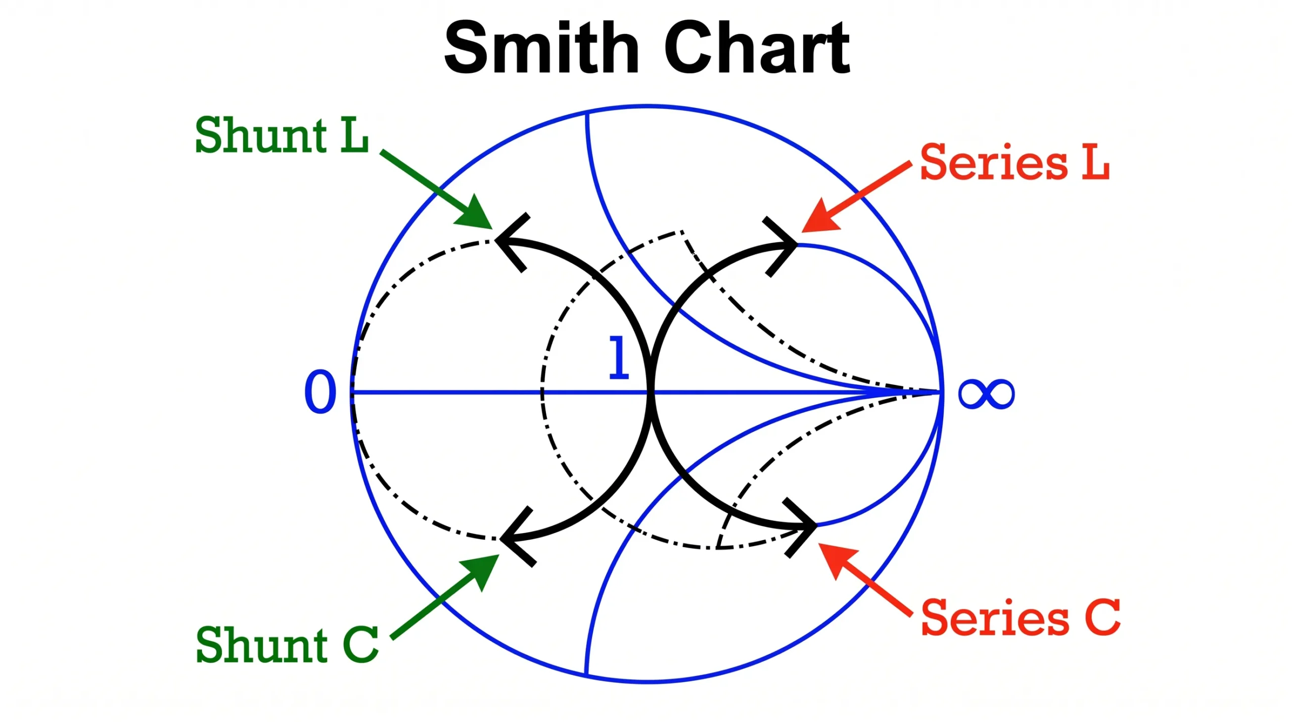
cURL Too many subrequests by single Worker invocation. To configure this limit, refer to https://developers.cloudflare.com/workers/wrangler/configuration/#limits. cURL Too many subrequests by single Worker invocation. To configure this limit, refer to https://developers.cloudflare.com/workers/wrangler/configuration/#limits5, cURL Too many subrequests by single Worker invocation. To configure this limit, refer to https://developers.cloudflare.com/workers/wrangler/configuration/#limits.
cURL Too many subrequests by single Worker invocation. To configure this limit, refer to https://developers.cloudflare.com/workers/wrangler/configuration/#limits
cURL Too many subrequests by single Worker invocation. To configure this limit, refer to https://developers.cloudflare.com/workers/wrangler/configuration/#limits.
| cURL Too many subrequests by single Worker invocation. To configure this limit, refer to https://developers.cloudflare.com/workers/wrangler/configuration/#limits | cURL Too many subrequests by single Worker invocation. To configure this limit, refer to https://developers.cloudflare.com/workers/wrangler/configuration/#limits |
|---|---|
| cURL Too many subrequests by single Worker invocation. To configure this limit, refer to https://developers.cloudflare.com/workers/wrangler/configuration/#limits | cURL Too many subrequests by single Worker invocation. To configure this limit, refer to https://developers.cloudflare.com/workers/wrangler/configuration/#limits up cURL Too many subrequests by single Worker invocation. To configure this limit, refer to https://developers.cloudflare.com/workers/wrangler/configuration/#limits |
| Series Capacitor | cURL Too many subrequests by single Worker invocation. To configure this limit, refer to https://developers.cloudflare.com/workers/wrangler/configuration/#limits down cURL Too many subrequests by single Worker invocation. To configure this limit, refer to https://developers.cloudflare.com/workers/wrangler/configuration/#limits |
| Shunt Inductor | cURL Too many subrequests by single Worker invocation. To configure this limit, refer to https://developers.cloudflare.com/workers/wrangler/configuration/#limits down along a constant-conductance circle |
| Shunt Capacitor | cURL Too many subrequests by single Worker invocation. To configure this limit, refer to https://developers.cloudflare.com/workers/wrangler/configuration/#limits up along a constant-conductance circle |
Let's imagine your initial measurement plots a point in the lower-right quadrant of the chart. The chart might show that adding a series inductor first will move the point upward onto the main "1.0" circle. From there, adding a shunt capacitor will move the point along that circle toward the center. The Smith Chart software or formulas will even tell you the exact values (in nanohenries or picofarads) needed for each step. You can then select the closest standard component values and place them in the footprints you wisely left on your PCB. This methodical process turns a complex RF problem into a simple, step-by-step procedure.
Conclusión
Successful LNB integration isn't just about the LNB's specs. It's about proactive design, proper matching, and treating the Bias-Tee and LNB as a single, optimized system.
"SNR Degradation in Undersampled Phase Measurement Systems", https://pmc.ncbi.nlm.nih.gov/articles/PMC5087556/. A source can confirm that impedance mismatch between the LNB and preceding components like the bias-tee is a well-documented cause of performance degradation, leading to increased noise figure and reduced signal-to-noise ratio. Evidence role: general_support; source type: paper. Supports: That impedance mismatch at the LNB input, particularly from components like the bias-tee, is a recognized and significant cause of signal-to-noise ratio (SNR) degradation in satellite communication systems.. ↩
"[PDF] High-Speed PCB Design Guide - S3VI", https://s3vi.ndc.nasa.gov/ssri-kb/static/resources/High-Speed%20PCB%20Design%20Guide.pdf. A source can explain that a large conductive pad over a ground plane forms a parallel plate capacitor, creating unwanted parasitic capacitance at high frequencies. Removing the ground plane directly underneath the pad is a standard RF PCB design technique to mitigate this effect. Evidence role: mechanism; source type: education. Supports: That removing the ground plane beneath a large surface-mount pad reduces the parasitic capacitance formed between the pad and the ground plane.. ↩
"Tapered radio frequency transmission lines - PDXScholar", https://pdxscholar.library.pdx.edu/cgi/viewcontent.cgi?article=5339&context=open_access_etds. A source can describe the principle of tapered inductors or transmission lines, explaining that their gradually changing geometry creates a smooth impedance transition, which is effective for achieving broadband matching between two different impedances. Evidence role: definition; source type: paper. Supports: That tapered inductors or transmission lines are designed to function as an impedance transformer over a broad range of frequencies by providing a gradual change in characteristic impedance.. ↩
"Pi network Vs T network : r/rfelectronics - Reddit", https://www.reddit.com/r/rfelectronics/comments/eiywrv/pi_network_vs_t_network/. A textbook or educational resource on RF circuit design can confirm that the π-network topology is commonly employed to match a higher impedance to a lower one, due to its component configuration and quality factor (Q) characteristics. Evidence role: general_support; source type: education. Supports: That π-networks are particularly well-suited for impedance matching circuits where the source impedance is higher than the load impedance.. Scope note: While this is a common use case, the π-network can be used in other scenarios as well; the source would support this as a primary application. ↩
"Impedance and admittance circles on the Smith Chart - Ximera", https://ximera.osu.edu/electromagnetics/electromagnetics/smithChart/digInSmithChartDerivationImpedanceAdmittance. A source can explain that the Smith Chart is a graphical tool where impedance values are normalized to the system's characteristic impedance (Z₀). The center of the chart (1+j0) represents a perfect match to Z₀, which is standardized as 50 ohms in the majority of RF and microwave applications. Evidence role: definition; source type: encyclopedia. Supports: That the center of a Smith Chart represents the normalized system impedance, which corresponds to a perfect match (zero reflection), and in most RF systems, this is 50 ohms.. ↩
