
Getting inaccurate BUC power readings? These errors can mess up your link budget and performance assessments. Follow these tips to ensure your spectrum analyzer gives you the right numbers.
To accurately measure BUC output power, first connect a high-power external attenuator to protect your equipment. Then, use a calibrated spectrum analyzer and avoid overloading its input mixer. You can verify accuracy by adjusting the analyzer's internal attenuator and checking for changes in the measured power.
I've spent countless hours in the lab, and I've seen how a seemingly small measurement error can cause big headaches down the line. It's not just about protecting expensive gear; it's about trusting the data that guides your entire system design. Let's explore why this precision is so non-negotiable and how to achieve it.
Why is a Few dB of Measurement Error a Big Deal?
Ever thought a 1 or 2 dB measurement error was acceptable? This small mistake can compromise your entire link budget1 and misrepresent non-linear performance, leading to system failure.
A small power measurement error directly impacts your satellite link budget calculations, affecting signal availability during adverse conditions. It also skews evaluations of non-linear metrics like OIP3 and ACPR, which are crucial for system compliance and performance. Getting it right is essential for reliable communication.

In my 20 years of engineering, I've learned that precision is everything. An error of just 1 or 2 dB in your BUC's output power measurement isn't a minor detail; it's a critical flaw. Think about the link budget for a satellite connection. That budget has a built-in margin to handle things like heavy rain, known as rain fade2. If your power measurement is 2 dB higher than the actual output, your real-world link margin is 2 dB lower than you calculated. This could be the difference between a working connection and a complete outage during a storm.
The problem also extends to non-linear performance. Key metrics like the 1 dB compression point (P1dB)3 and Adjacent Channel Power Ratio (ACPR) are defined by the BUC's output power. If your power reference is wrong, your entire characterization of the BUC is wrong. You might think the BUC is operating linearly when it's actually in compression, creating distortion and interfering with adjacent channels4. This can lead to non-compliance with regulations and poor system performance. At Safari Microwave, when we test our 3000W high-power BUCs, we know that a tiny percentage error translates into a huge absolute power error, so we live by these principles.
The Real-World Impact of Measurement Errors
| Impact Area | Consequence of a +2 dB Measurement Error | Hvorfor det betyder noget |
|---|---|---|
| Link Budget | Your calculated link margin is 2 dB higher than reality. | The system might fail during rain fade or other atmospheric events. |
| Non-Linearity | P1dB and OIP3 points appear higher than they are. | You might operate the BUC too close to its compression point, causing distortion. |
| ACPR/Spurious | Measured adjacent channel power might seem compliant when it isn't. | Causes interference to other users and can result in regulatory fines. |
| Effektivitet | Calculated Power Added Efficiency (PAE)5 will be artificially inflated. | You might make poor design choices based on incorrect efficiency data. |
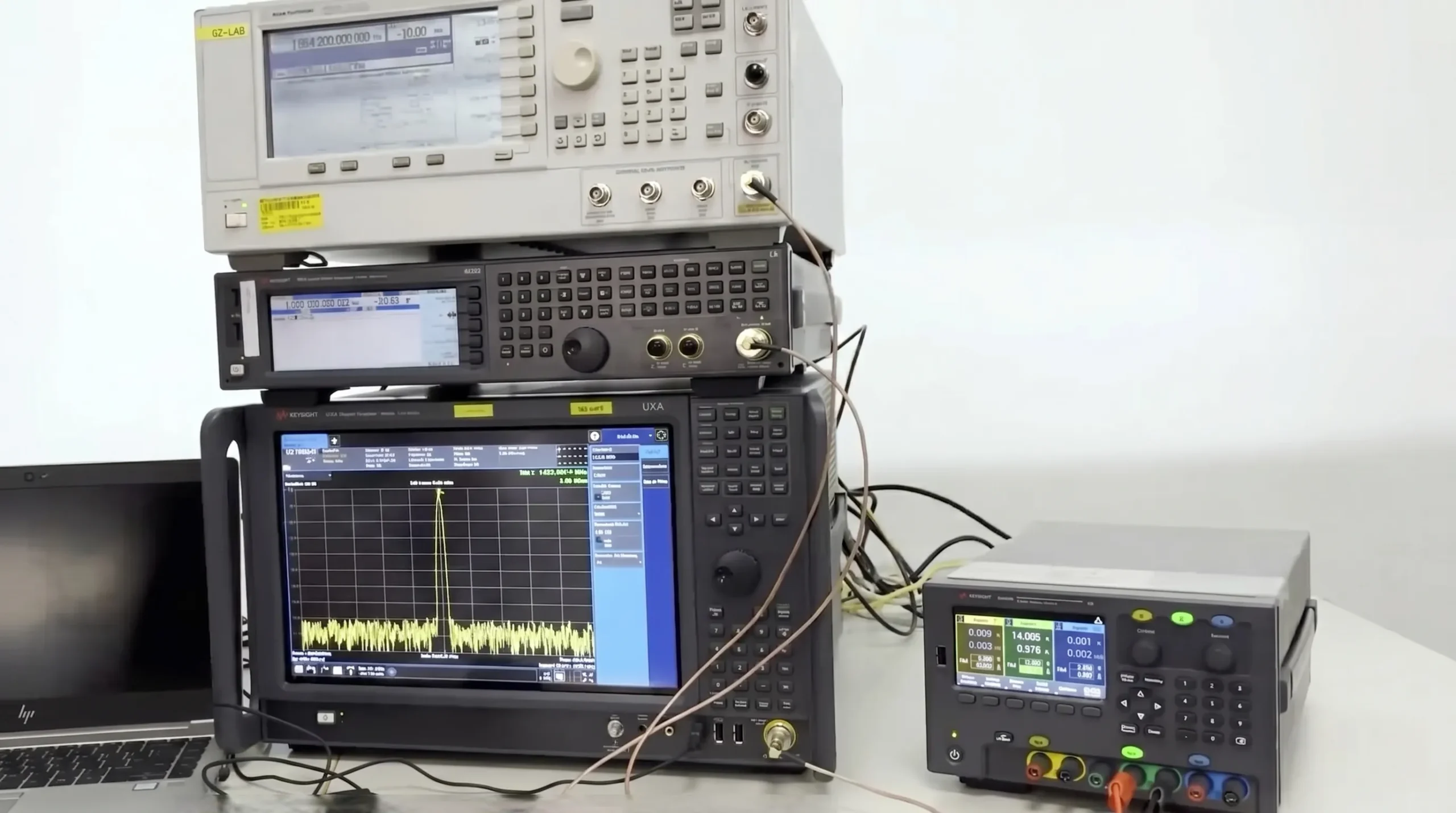
How Do You Properly Set Up Your Test Equipment for High Power?
Ready to measure your BUC output? Connecting it directly to a spectrum analyzer is a recipe for disaster. The high power will instantly fry the sensitive input mixer.
First, connect a high-power attenuator, rated for more than your BUC's maximum output, directly to the BUC output. Then, add coaxial cables and any additional low-power attenuators needed to bring the signal down to a safe level for your calibrated spectrum analyzer's input.
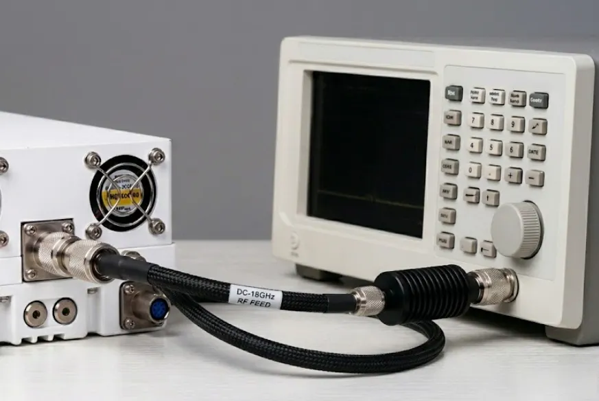
I remember a junior engineer early in my career who learned this lesson the hard way. The smell of a burned-out mixer in a $50,000 spectrum analyzer is something you don't forget. Protecting your test equipment is the first step, and it requires a methodical approach. The hero of this setup is the high-power external attenuator. Its job is to take the massive power from the BUC—sometimes thousands of watts—and safely convert most of it into heat. You must choose an attenuator with a power rating significantly higher than your BUC's maximum output. A 20-30% safety margin is a good rule of thumb.
Next, you have to account for the loss of every single component in your test chain. This includes the main high-power attenuator, all connecting cables, and any adapters. The best practice is to cURL Too many subrequests by single Worker invocation. To configure this limit, refer to https://developers.cloudflare.com/workers/wrangler/configuration/#limits6 cURL Too many subrequests by single Worker invocation. To configure this limit, refer to https://developers.cloudflare.com/workers/wrangler/configuration/#limits.
cURL Too many subrequests by single Worker invocation. To configure this limit, refer to https://developers.cloudflare.com/workers/wrangler/configuration/#limits
| cURL Too many subrequests by single Worker invocation. To configure this limit, refer to https://developers.cloudflare.com/workers/wrangler/configuration/#limits | cURL Too many subrequests by single Worker invocation. To configure this limit, refer to https://developers.cloudflare.com/workers/wrangler/configuration/#limits | cURL Too many subrequests by single Worker invocation. To configure this limit, refer to https://developers.cloudflare.com/workers/wrangler/configuration/#limits |
|---|---|---|
| 1 | cURL Too many subrequests by single Worker invocation. To configure this limit, refer to https://developers.cloudflare.com/workers/wrangler/configuration/#limits | cURL Too many subrequests by single Worker invocation. To configure this limit, refer to https://developers.cloudflare.com/workers/wrangler/configuration/#limits. |
| 2 | cURL Too many subrequests by single Worker invocation. To configure this limit, refer to https://developers.cloudflare.com/workers/wrangler/configuration/#limits | cURL Too many subrequests by single Worker invocation. To configure this limit, refer to https://developers.cloudflare.com/workers/wrangler/configuration/#limits. |
| 3 | cURL Too many subrequests by single Worker invocation. To configure this limit, refer to https://developers.cloudflare.com/workers/wrangler/configuration/#limits | cURL Too many subrequests by single Worker invocation. To configure this limit, refer to https://developers.cloudflare.com/workers/wrangler/configuration/#limits. |
| 4 | cURL Too many subrequests by single Worker invocation. To configure this limit, refer to https://developers.cloudflare.com/workers/wrangler/configuration/#limits | cURL Too many subrequests by single Worker invocation. To configure this limit, refer to https://developers.cloudflare.com/workers/wrangler/configuration/#limits. |
cURL Too many subrequests by single Worker invocation. To configure this limit, refer to https://developers.cloudflare.com/workers/wrangler/configuration/#limits
cURL Too many subrequests by single Worker invocation. To configure this limit, refer to https://developers.cloudflare.com/workers/wrangler/configuration/#limits.
cURL Too many subrequests by single Worker invocation. To configure this limit, refer to https://developers.cloudflare.com/workers/wrangler/configuration/#limits, cURL Too many subrequests by single Worker invocation. To configure this limit, refer to https://developers.cloudflare.com/workers/wrangler/configuration/#limits7, cURL Too many subrequests by single Worker invocation. To configure this limit, refer to https://developers.cloudflare.com/workers/wrangler/configuration/#limits.
cURL Too many subrequests by single Worker invocation. To configure this limit, refer to https://developers.cloudflare.com/workers/wrangler/configuration/#limits.
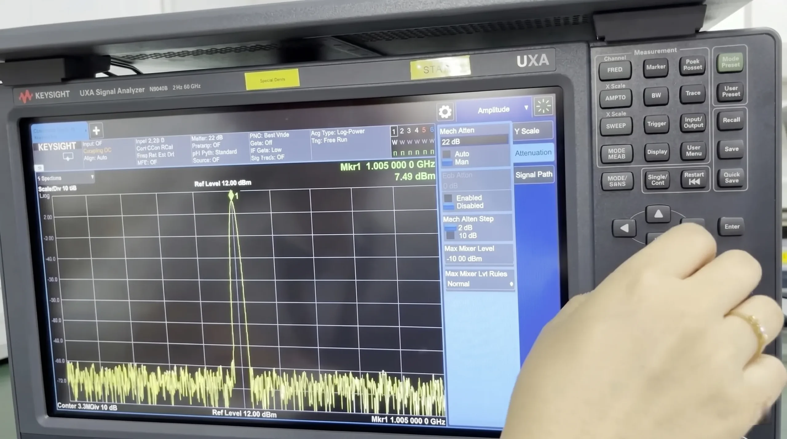
cURL Too many subrequests by single Worker invocation. To configure this limit, refer to https://developers.cloudflare.com/workers/wrangler/configuration/#limits cURL Too many subrequests by single Worker invocation. To configure this limit, refer to https://developers.cloudflare.com/workers/wrangler/configuration/#limits to something like +15.4 dBm, it means your original reading was compressed by 0.4 dB. The second reading is the more accurate one. You can trust it, and you should use this new, higher internal attenuation setting for all your measurements.
Konklusion
Achieving precise BUC power measurement requires strict test bench integrity. A robust methodology—utilizing precision high-power attenuators, calibrated analyzers, and active prevention of mixer overload—is essential to eliminate measurement errors. This rigorous approach is the only way to verify true linear power and ensure uncompromising system reliability.
"Satellite Link Budget - MATLAB & Simulink - MathWorks", https://www.mathworks.com/help/satcom/gs/satellite-link-budget.html. A source can provide a standard satellite link budget calculation, showing how parameters like transmit power (EIRP), path loss, and receiver sensitivity (G/T) are summed, and how the final link margin is a small positive dB value. This demonstrates that a 1-2 dB error in measuring transmit power directly subtracts from this critical margin. Evidence role: mechanism; source type: education. Supports: The claim that a small dB error can compromise a link budget.. ↩
"What is Rain Fade? - everything RF", https://www.everythingrf.com/community/what-is-rain-fade. A source, such as a recommendation from the International Telecommunication Union (ITU), can define rain fade as the absorption and scattering of microwave signals by hydrometeors (rain, snow, ice) in the atmosphere, which causes signal attenuation that increases with frequency and rain intensity. Evidence role: definition; source type: institution. Supports: The definition and cause of rain fade.. ↩
"What is P1dB? - everything RF", https://www.everythingrf.com/community/what-is-p1db. A source can define the 1 dB compression point (P1dB) as the output power level at which the amplifier's actual gain has dropped by 1 dB compared to its small-signal linear gain, indicating the onset of non-linear behavior and saturation. Evidence role: definition; source type: education. Supports: The definition of the 1 dB compression point (P1dB).. ↩
"Adjacent-channel interference", https://en.wikipedia.org/wiki/Adjacent-channel_interference. A source can explain that as an amplifier enters compression, it generates intermodulation distortion products and spectral regrowth, which are unwanted signals that spread out from the intended signal and can fall into adjacent frequency channels, causing interference. Evidence role: mechanism; source type: paper. Supports: The mechanism by which amplifier compression causes adjacent channel interference.. ↩
"Power-added efficiency - Wikipedia", https://en.wikipedia.org/wiki/Power-added_efficiency. A source can define Power Added Efficiency (PAE) and provide its formula: PAE = (P_out - P_in) / P_DC. This equation shows that PAE is directly proportional to the measured output power (P_out), confirming that an erroneously high P_out measurement will result in an artificially inflated efficiency calculation. Evidence role: definition; source type: education. Supports: The definition and formula for Power Added Efficiency (PAE).. ↩
"A de-embedding method based on combining time and frequency ...", https://pmc.ncbi.nlm.nih.gov/articles/PMC12119982/. A source can describe how a Vector Network Analyzer (VNA) measures the S-parameters of a device under test, with the S21 parameter directly representing the insertion loss (or gain) across a range of frequencies. This method allows for a precise, frequency-specific characterization of all passive components in the test path. Evidence role: mechanism; source type: paper. Supports: The use of a VNA to characterize the insertion loss of a test chain.. ↩
"Learn How to Improve Your Mix with Spectrum Analyzers", https://www.iconcollective.edu/spectrum-analyzers. A source, such as an application note from a spectrum analyzer manufacturer, can explain that an overloaded mixer exhibits gain compression, causing it to report a power level lower than the actual input. When internal attenuation is added, the power at the mixer is reduced back into its linear range, and the analyzer's corrected reading becomes accurate. A change in the reading upon adding attenuation is therefore a direct indication of initial compression. Evidence role: mechanism; source type: other. Supports: The mechanism behind the internal attenuation test for mixer overload.. ↩
