
Feeling overwhelmed by spurious signals in your RF designs? You're not alone. The unpredictable nature of spurs can ruin performance and cause major headaches for any engineer.
You can demystify intermodulation by understanding it's a predictable result of mixer nonlinearity1. Use mixer spurious charts and simulation software like ADS to select frequencies that avoid spurs. Also, keep the mixer's input power well within its linear range to minimize them.
This sounds simple, but let's break it down. I remember a project early in my career where a mysterious spur nearly derailed our entire timeline. It was a frustrating experience, but it taught me a valuable lesson: understanding the fundamentals is the only way to truly control your design. That project forced me to go back to basics and learn how to predict and manage these unwanted signals. Let's start with what causes them in the first place.
What Exactly Causes These Spurious Signals in a Mixer?
Are random signals appearing in your output spectrum? These "spurs" can seem to come from nowhere, making your design unreliable and difficult to troubleshoot.
Spurious signals are not random. They are mathematically predictable results of the non-linear behavior of a mixer. When you mix two frequencies (RF and LO), you also create a series of unwanted harmonic products (mRF ± nLO)2, which are the spurs.
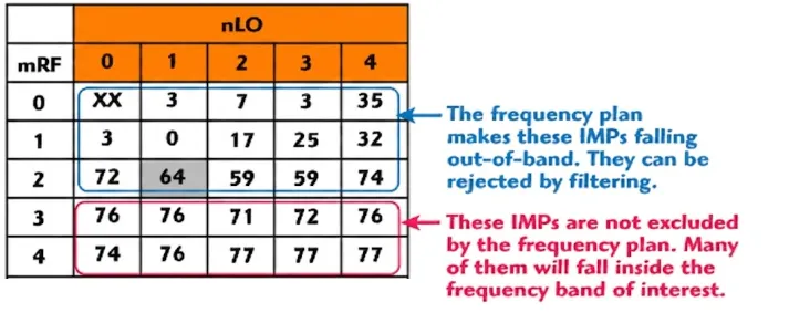
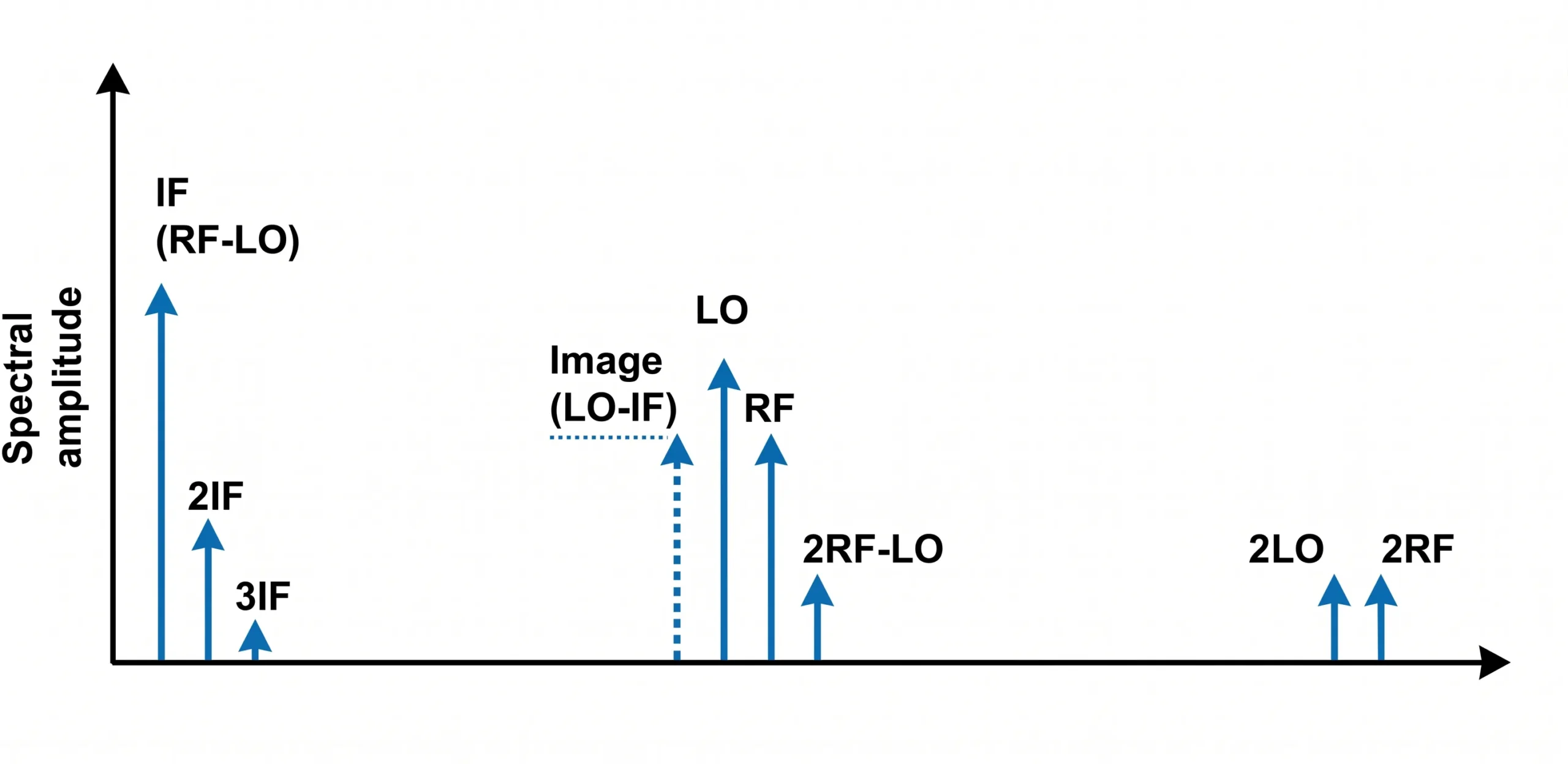
To really get this, we have to look at how a real mixer works. An ideal mixer would only produce two outputs: the sum and difference of the input frequencies (LO + RF and LO - RF). But real-world mixers are not perfectly linear. Their behavior is better described by a power series equation. The output signal contains not just the desired mixed frequencies but also harmonics of the inputs and the intermodulation products of those harmonics. This is where the famous F_IF = m*F_LO ± n*F_RF equation comes from. Here, 'm' and 'n' are integers representing the harmonic orders. When m=1 and n=1, you get your desired signal. All other combinations are spurious products. A mixer spurious chart is a visual tool that maps these products.3 It helps you see where potential spurs will land based on your chosen RF, LO, and IF frequencies.
| m (LO Harmonic) | n (RF Harmonic) | Spur Product Example |
|---|---|---|
| 1 | 1 | LO ± RF (Desired IF) |
| 2 | 2 | 2LO ± 2RF |
| 3 | 1 | 3LO ± RF |
| 1 | 3 | LO ± 3RF |
| 3 | 2 | 3LO ± 2RF |
I always start my downconverter designs with a spur chart. It is like a map that shows me where the trouble spots are before I even begin.
How Can You Use a Spur Chart to Plan Your Frequencies?
Choosing frequencies feels like a guessing game sometimes. Pick the wrong LO, and your IF band is suddenly cluttered with spurs, forcing a complete redesign.
Use a mixer spurious chart as your guide. First, define your desired RF input and IF output frequency ranges. Then, overlay this information onto the chart to find an LO frequency "window" that keeps major spurs out of your IF band.

This is a critical "paper" exercise that saves countless hours later. Let’s walk through a simple example. Imagine you need to downconvert an RF signal at 10 GHz to an IF of 1 GHz. You have two primary choices for your Local Oscillator (LO) frequency.
High-Side vs. Low-Side Injection
- Low-Side Injection: You set your LO to 9 GHz. Your IF is
F_RF - F_LO= 10 GHz - 9 GHz = 1 GHz. - High-Side Injection: cURL Too many subrequests by single Worker invocation. To configure this limit, refer to https://developers.cloudflare.com/workers/wrangler/configuration/#limits
cURL Too many subrequests by single Worker invocation. To configure this limit, refer to https://developers.cloudflare.com/workers/wrangler/configuration/#limitscURL Too many subrequests by single Worker invocation. To configure this limit, refer to https://developers.cloudflare.com/workers/wrangler/configuration/#limits.
cURL Too many subrequests by single Worker invocation. To configure this limit, refer to https://developers.cloudflare.com/workers/wrangler/configuration/#limitscURL Too many subrequests by single Worker invocation. To configure this limit, refer to https://developers.cloudflare.com/workers/wrangler/configuration/#limits).
| cURL Too many subrequests by single Worker invocation. To configure this limit, refer to https://developers.cloudflare.com/workers/wrangler/configuration/#limits | cURL Too many subrequests by single Worker invocation. To configure this limit, refer to https://developers.cloudflare.com/workers/wrangler/configuration/#limits | cURL Too many subrequests by single Worker invocation. To configure this limit, refer to https://developers.cloudflare.com/workers/wrangler/configuration/#limits | cURL Too many subrequests by single Worker invocation. To configure this limit, refer to https://developers.cloudflare.com/workers/wrangler/configuration/#limits | cURL Too many subrequests by single Worker invocation. To configure this limit, refer to https://developers.cloudflare.com/workers/wrangler/configuration/#limits |
|---|---|---|---|---|
| cURL Too many subrequests by single Worker invocation. To configure this limit, refer to https://developers.cloudflare.com/workers/wrangler/configuration/#limits | cURL Too many subrequests by single Worker invocation. To configure this limit, refer to https://developers.cloudflare.com/workers/wrangler/configuration/#limits | cURL Too many subrequests by single Worker invocation. To configure this limit, refer to https://developers.cloudflare.com/workers/wrangler/configuration/#limits | cURL Too many subrequests by single Worker invocation. To configure this limit, refer to https://developers.cloudflare.com/workers/wrangler/configuration/#limits | cURL Too many subrequests by single Worker invocation. To configure this limit, refer to https://developers.cloudflare.com/workers/wrangler/configuration/#limits |
| cURL Too many subrequests by single Worker invocation. To configure this limit, refer to https://developers.cloudflare.com/workers/wrangler/configuration/#limits | cURL Too many subrequests by single Worker invocation. To configure this limit, refer to https://developers.cloudflare.com/workers/wrangler/configuration/#limits | cURL Too many subrequests by single Worker invocation. To configure this limit, refer to https://developers.cloudflare.com/workers/wrangler/configuration/#limits | cURL Too many subrequests by single Worker invocation. To configure this limit, refer to https://developers.cloudflare.com/workers/wrangler/configuration/#limits | cURL Too many subrequests by single Worker invocation. To configure this limit, refer to https://developers.cloudflare.com/workers/wrangler/configuration/#limits |
cURL Too many subrequests by single Worker invocation. To configure this limit, refer to https://developers.cloudflare.com/workers/wrangler/configuration/#limits cURL Too many subrequests by single Worker invocation. To configure this limit, refer to https://developers.cloudflare.com/workers/wrangler/configuration/#limits4. cURL Too many subrequests by single Worker invocation. To configure this limit, refer to https://developers.cloudflare.com/workers/wrangler/configuration/#limits.
How Do You Verify Your Frequency Plan with ADS Simulation?
cURL Too many subrequests by single Worker invocation. To configure this limit, refer to https://developers.cloudflare.com/workers/wrangler/configuration/#limits.
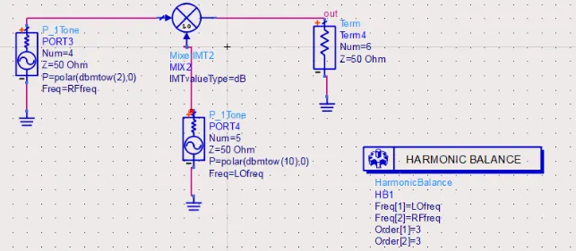
Use simulation software like Keysight ADS. Set up a Harmonic Balance simulation with your chosen mixer, LO, and RF signals.5 This allows you to perform a full frequency sweep and visualize all the output spurs, verifying your initial frequency plan.
This is where the real verification happens. I consider ADS an essential tool in my design process. It bridges the gap between theory and reality.
Setting Up the Simulation in ADS
First, I build a simple schematic. This includes a power source for the RF signal, another for the LO signal, a model for the mixer, and a termination for the IF port. For the mixer, you can start with a basic behavioral model or, for better accuracy, use a data-based model provided by the component manufacturer like Safari Microwave.
Using the Harmonic Balance Controller
Next, I add a Harmonic Balance (HB) controller. This is the heart of the simulation. In the HB controller, I define the fundamental frequencies, which are my LO and RF frequencies. I also specify the number of harmonics to calculate. A higher number gives more accuracy for high-order spurs but increases simulation time.6 I usually start with 7 or 9 harmonics for both LO and RF, which is a good balance.
Sweeping and Visualizing Results
The most powerful feature is the parameter sweep. I set up a sweep to vary the RF frequency across its entire operational band. After running the simulation, I plot the spectrum at the IF output port. You will see a large spike for your desired 1 GHz IF signal. Then you will see a series of smaller spikes scattered around. These are your spurs. The beauty of this is that you can now compare your simulation results directly to the spur chart you made earlier. The big spurs you identified on paper should appear exactly where the math predicted they would.
What If You Cannot Avoid In-Band Spurs?
Sometimes, no matter how you plan your frequencies, a critical spur lands right in your passband. This can seem like a dead end for your design.
If you can't avoid an in-band spur, you must manage its power level. Force the mixer to operate in its linear region by keeping the input power low. A good rule is to keep the RF input at least 15 dB below the mixer's P1dB compression point7.

Even the best frequency plan can sometimes lead to a compromise where a low-order spur falls into your IF band. When this happens, you have to shift your strategy from avoidance to mitigation. The key is to control the mixer's operating point.
The Power of Linearity
A mixer's 1dB compression point (P1dB) tells you when it starts to become non-linear8. The further you operate below this point, the more linearly the mixer behaves. This has a dramatic effect on spur levels. For every 1 dB you decrease the input power, a third-order intermodulation product will decrease by 3 dB9. A fifth-order product will decrease by 5 dB. This gives you a powerful lever to push down the level of unwanted in-band spurs.
Practical Implementation in ADS
I use ADS to confirm this and find the precise input power limit. Go back to the ADS schematic we built. Instead of a frequency sweep, set up a power sweep on the RF input source. You can then plot two things on the same graph: the output power of your desired IF signal and the output power of the problematic in-band spur, both as a function of the RF input power. You will clearly see the spur's power level dropping much faster than your desired signal's power. This simulation confirms the "15 dB below P1dB" rule of thumb and helps you define the maximum allowable input power for your system to meet its spurious-free dynamic range (SFDR) specification10.
མཇུག་སྡོམ།
Spurious signals are not black magic; they are predictable. Use spur charts for planning, ADS for verification, and control input power to manage unavoidable in-band spurs. This systematic approach works.
"Intermodulation - Wikipedia", https://en.wikipedia.org/wiki/Intermodulation. Sources in electrical engineering explain that the nonlinear voltage-current characteristic of a mixer's internal components, when analyzed with a power series expansion, mathematically predicts the generation of harmonic and intermodulation frequencies beyond the desired sum and difference outputs. Evidence role: mechanism; source type: education. Supports: The claim that spurious signals (intermodulation products) are a predictable outcome of the inherent nonlinear characteristics of an RF mixer.. ↩
"Intermodulation Products for a Mixer Subjected to a Multi-carrier Signal", https://www.microwavejournal.com/articles/3393-intermodulation-products-for-a-mixer-subjected-to-a-multi-carrier-signal. Technical literature on RF mixers confirms that intermodulation distortion products can be categorized by the equation F_out = m*F1 ± n*F2, where F1 and F2 are the input frequencies (e.g., LO and RF) and m and n are the integer orders of their respective harmonics. Evidence role: definition; source type: paper. Supports: The claim that spurious products generated by a mixer can be expressed by the general formula F_spur = m*F_LO ± n*F_RF, where m and n are integers.. ↩
"A Brief Guide to Mixer Spurs - Marki Microwave", https://markimicrowave.com/technical-resources/multimedia/webinars/brief-guide-mixer-spurs/. Component datasheets and RF design application notes define a mixer spurious chart (or 'spur chart') as a graphical representation that plots the frequency of various intermodulation products (m*LO ± n*RF) against a chosen variable, typically the RF or LO frequency, to aid in frequency planning. Evidence role: definition; source type: other. Supports: The claim that a mixer spurious chart is a graphical tool for visualizing the locations of intermodulation products.. ↩
"high side injection and low side injection in mixer", https://www.edaboard.com/threads/high-side-injection-and-low-side-injection-in-mixer.125131/. RF design guides and application notes illustrate through examples that selecting high-side versus low-side injection can shift the location of problematic spurs, such as the half-IF spur (2RF - 2LO), either into or out of the desired passband, making the choice a critical step in frequency planning. Evidence role: case_reference; source type: paper. Supports: The claim that the choice between high-side and low-side injection has a significant effect on which spurious products land in the desired intermediate frequency (IF) band.. ↩
"[PDF] ADS and Circuit Simulation Fundamentals", http://class.ece.iastate.edu/djchen/ee507/ADSCircuitSimulation.pdf. Technical documentation and research papers on RF simulation confirm that the Harmonic Balance method is a frequency-domain analysis technique well-suited for simulating non-linear circuits driven by multiple tones, such as mixers, allowing for the accurate prediction of intermodulation spurs. Evidence role: general_support; source type: research. Supports: The claim that Harmonic Balance (HB) simulation is a standard method for analyzing and predicting spurious products in RF mixer circuits.. ↩
"[PDF] Harmonic Balance Simulation on ADS", https://web.ece.ucsb.edu/Faculty/rodwell/Classes/ece218b/tutorials_etc/ADS_Harmonic_Balance.pdf. Simulation software documentation explains that the 'order' or number of harmonics set in a Harmonic Balance controller determines the fidelity of the simulation. A higher order is required to accurately model sharp-edged signals or high-order intermodulation products, but it increases the size of the system of equations to be solved, thus extending computation time. Evidence role: mechanism; source type: other. Supports: The claim that there is a trade-off between accuracy and simulation time when selecting the number of harmonics in a Harmonic Balance simulation.. ↩
"Active Mixer RF Input Power and Input IP3i, P1dB Question", https://electronics.stackexchange.com/questions/461351/active-mixer-rf-input-power-and-input-ip3i-p1db-question. RF design guides often recommend operating a mixer well within its linear region to control spurious products. While specific values vary, a common guideline is to keep the total input power 10 to 20 dB below the mixer's P1dB point to ensure that intermodulation distortion does not degrade system performance. Evidence role: general_support; source type: education. Supports: The claim that keeping input power significantly below the P1dB point is a common design rule for minimizing spurious signals.. Scope note: The exact '15 dB' figure is a rule of thumb; sources may recommend a range (e.g., 10-20 dB) depending on the specific application and system requirements. ↩
"What is P1dB? - everything RF", https://www.everythingrf.com/community/what-is-p1db. Technical encyclopedias and glossaries define the 1dB compression point (P1dB) as the input power level at which the actual output power of a device has dropped by 1 dB from the theoretical linear output. This point is a standard figure of merit for characterizing the limit of linear operation in RF components like mixers and amplifiers. Evidence role: definition; source type: encyclopedia. Supports: The claim that the 1dB compression point (P1dB) is the point at which a device's response begins to show significant nonlinearity.. ↩
"Third-order intercept point - Wikipedia", https://en.wikipedia.org/wiki/Third-order_intercept_point. The theory of intermodulation distortion in nonlinear systems shows that, for small input signals, the power of the nth-order product is proportional to the input power raised to the nth power. In a logarithmic (dB) scale, this means a 1 dB change in input power results in an n-dB change in the power of the nth-order intermodulation product. Evidence role: mechanism; source type: education. Supports: The claim that an nth-order intermodulation product's power level changes by n dB for every 1 dB change in input power.. ↩
"Spurious-free dynamic range - Wikipedia", https://en.wikipedia.org/wiki/Spurious-free_dynamic_range. Technical sources define Spurious-Free Dynamic Range (SFDR) as the ratio of the power of the fundamental signal to the power of the strongest spurious signal in the output. It is a critical metric that quantifies the range over which a system can operate without spurious signals interfering with the desired signal, and it is directly limited by the level of intermodulation products. Evidence role: definition; source type: encyclopedia. Supports: The claim that Spurious-Free Dynamic Range (SFDR) is a key specification related to intermodulation spurs.. ↩
