
Starting your RF amplifier design directly in simulation software1? This common mistake leads to frustrating dead ends and wasted time when your topology fails under real-world conditions.
The best process starts by defining detailed specifications based on the application. Then, you select the right transistor and topology. This is followed by simulation, layout, fabrication, and finally, rigorous testing to validate that the initial requirements have been met.
That's the high-level overview, but success is found in the details. As an engineer with 30 years of experience, I've seen many projects go sideways by skipping the most critical first step. It's tempting to jump into a tool like ADS, but that's like an architect trying to build a skyscraper without a blueprint. Let's break down the process I use at Safari Microwave to ensure we get it right every time, starting with the foundation of any great amplifier: the specifications.
How Do You Define the Right Specifications for Your RF Amplifier?
Vague specs can lead to an amplifier that doesn't perform in its intended application. You might build a technically perfect amp that fails in the field, costing you time and money.
First, focus on the application. Consider the system it will be a part of, the signal type (e.g., 5G NR, CW), and the environment. Key specs include frequency, output power, gain, efficiency, linearity (གཞན་ནས་སྤྱོད་རྣམ་ལ།2, ACLR3), and input/output matching4.
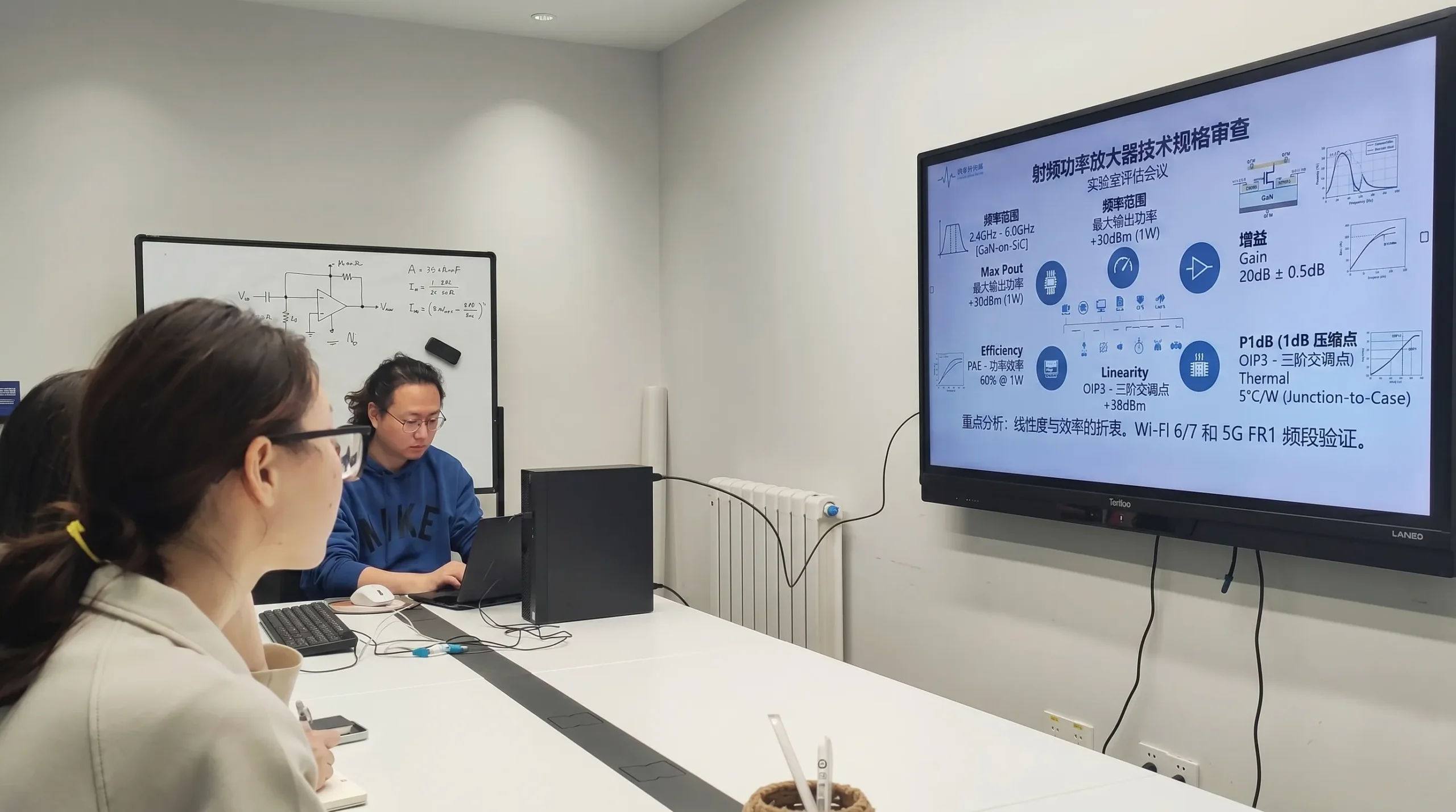
I can't stress this enough: do not start without a crystal-clear understanding of the end-use case. Many engineers, especially those early in their careers, get a list of target numbers and immediately start designing. This is a mistake. The numbers only tell part of the story. For example, a client once asked us for a 100-watt amplifier. But they didn't specify the signal type. A 100W CW amplifier is a completely different beast from a 100W amplifier for a 5G signal with a high Peak-to-Average Power Ratio (PAPR). The latter requires excellent ལག་ཆས་ལུ་སྤེལ་དུས་ཆེད་གྱི་ལོག་ཏོག་ལས་གསར་པ5 far below its peak power, something that can be easily missed. This is why you must think like the user.
Key Specification Areas
You need to break down the requirements into several key areas to build a complete picture.
- Electrical Specifications: This is the core of the design. You need to define every parameter precisely.
- Environmental & Mechanical: Where and how will this amplifier be used? An amplifier for a lab bench has very different constraints than one mounted on a cell tower.
Here’s a table I use as a starting checklist:
| ལས་སྤྱོད་ནས་སྤྱོད་ལམ་གཅིག་བཟོ་བའི་སྤྱོད་ལམ། | Description | Why It's Critical |
|---|---|---|
| ཁྱེད་ཀྱི་དབང་འབྲེལ་ལས་འབྲེལ་འབད | The operating frequency band (e.g., 2.4 - 2.5 GHz). | Defines the fundamental operating limits and affects component selection. |
| Output Power (Pout) | The required power at the output, often specified as P1dB or Psat. | This is the primary function of a power amplifier. |
| མངའ་མཐར | The amplification factor, measured in dB. | Must be sufficient for the system chain, with good flatness across the band. |
| Efficiency (PAE/DE) | Power-Added Efficiency or Drain Efficiency. | Crucial for thermal management and operational cost, especially in high-power systems. |
| Linearity (EVM, ACLR) | How well the amplifier reproduces the input signal without distortion. | Essential for complex modulation schemes like in 5G or Wi-Fi to maintain data integrity. |
| cURL Too many subrequests by single Worker invocation. To configure this limit, refer to https://developers.cloudflare.com/workers/wrangler/configuration/#limits | cURL Too many subrequests by single Worker invocation. To configure this limit, refer to https://developers.cloudflare.com/workers/wrangler/configuration/#limits. | cURL Too many subrequests by single Worker invocation. To configure this limit, refer to https://developers.cloudflare.com/workers/wrangler/configuration/#limits. |
| cURL Too many subrequests by single Worker invocation. To configure this limit, refer to https://developers.cloudflare.com/workers/wrangler/configuration/#limits | cURL Too many subrequests by single Worker invocation. To configure this limit, refer to https://developers.cloudflare.com/workers/wrangler/configuration/#limits. | cURL Too many subrequests by single Worker invocation. To configure this limit, refer to https://developers.cloudflare.com/workers/wrangler/configuration/#limits. |
cURL Too many subrequests by single Worker invocation. To configure this limit, refer to https://developers.cloudflare.com/workers/wrangler/configuration/#limits.
How Do You Select the Best Transistor and Topology?
cURL Too many subrequests by single Worker invocation. To configure this limit, refer to https://developers.cloudflare.com/workers/wrangler/configuration/#limits.
cURL Too many subrequests by single Worker invocation. To configure this limit, refer to https://developers.cloudflare.com/workers/wrangler/configuration/#limits.
cURL Too many subrequests by single Worker invocation. To configure this limit, refer to https://developers.cloudflare.com/workers/wrangler/configuration/#limits.
cURL Too many subrequests by single Worker invocation. To configure this limit, refer to https://developers.cloudflare.com/workers/wrangler/configuration/#limits
cURL Too many subrequests by single Worker invocation. To configure this limit, refer to https://developers.cloudflare.com/workers/wrangler/configuration/#limits.
| མཐོང་རོལ། | cURL Too many subrequests by single Worker invocation. To configure this limit, refer to https://developers.cloudflare.com/workers/wrangler/configuration/#limits | cURL Too many subrequests by single Worker invocation. To configure this limit, refer to https://developers.cloudflare.com/workers/wrangler/configuration/#limits | เหมาะสำหรับ |
|---|---|---|---|
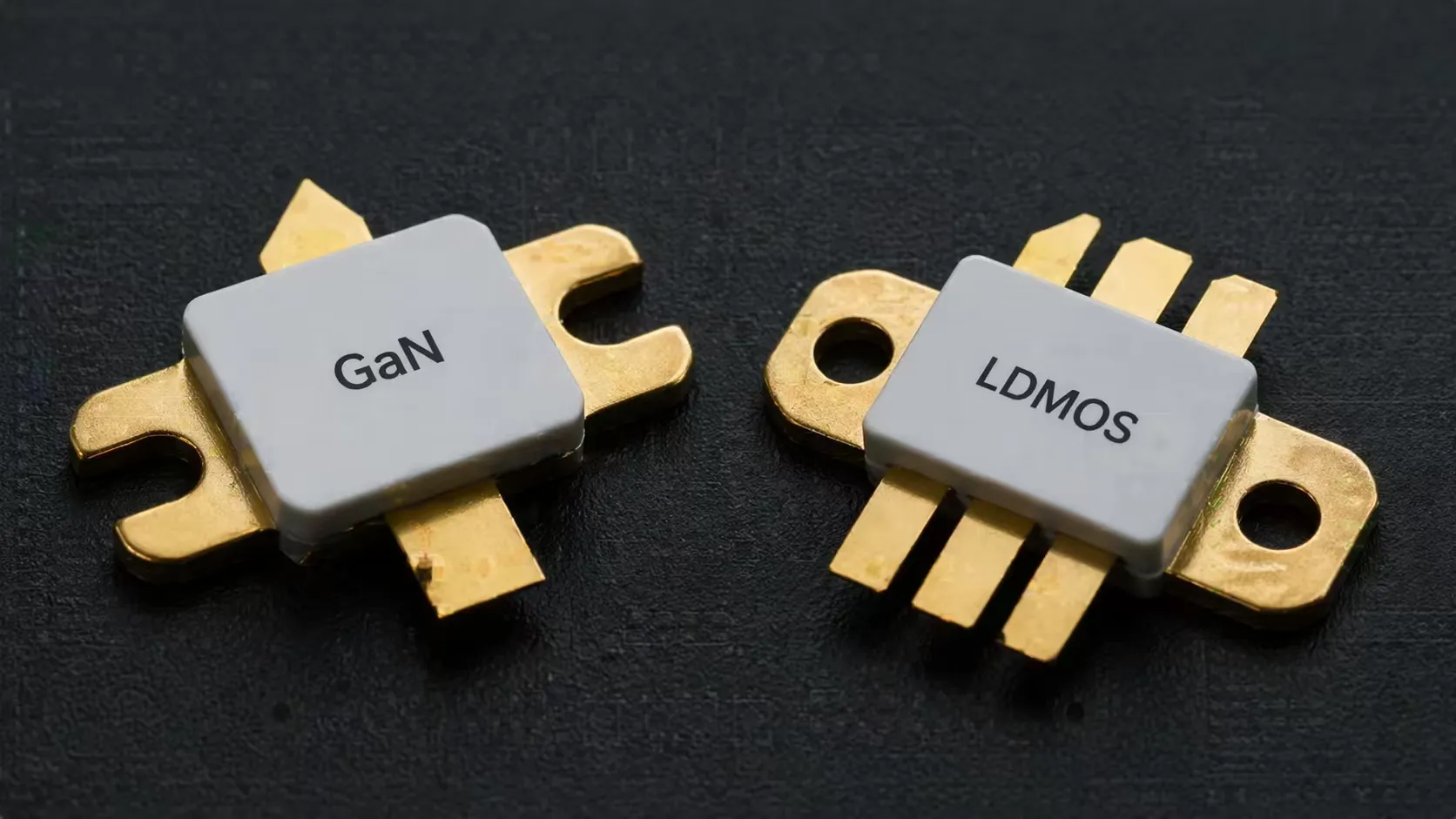
| GaN | cURL Too many subrequests by single Worker invocation. To configure this limit, refer to https://developers.cloudflare.com/workers/wrangler/configuration/#limits. | cURL Too many subrequests by single Worker invocation. To configure this limit, refer to https://developers.cloudflare.com/workers/wrangler/configuration/#limits. | cURL Too many subrequests by single Worker invocation. To configure this limit, refer to https://developers.cloudflare.com/workers/wrangler/configuration/#limits. |
| LDMOS | cURL Too many subrequests by single Worker invocation. To configure this limit, refer to https://developers.cloudflare.com/workers/wrangler/configuration/#limits. | cURL Too many subrequests by single Worker invocation. To configure this limit, refer to https://developers.cloudflare.com/workers/wrangler/configuration/#limits. | cURL Too many subrequests by single Worker invocation. To configure this limit, refer to https://developers.cloudflare.com/workers/wrangler/configuration/#limits. |
| GaAs | cURL Too many subrequests by single Worker invocation. To configure this limit, refer to https://developers.cloudflare.com/workers/wrangler/configuration/#limits. | cURL Too many subrequests by single Worker invocation. To configure this limit, refer to https://developers.cloudflare.com/workers/wrangler/configuration/#limits. | Handsets, linear amplifiers, low-noise amplifiers (LNAs). |
Choosing the Right Amplifier Class
After selecting the transistor, you choose the operating class, or topology. A simple Class AB amplifier is a reliable workhorse for many applications. But if your specs from step one demanded high efficiency at 8 dB of power back-off for a 5G signal, a Class AB design would be very inefficient. In that case, you would need a more advanced topology like a डोहर्टी एम्प्लिफायर6. This is a perfect example of why the initial spec-definition phase is so important. It directly guides these critical, foundational choices and prevents you from wasting weeks simulating a topology that was never going to work.
What Role Does Simulation and Layout Play in the Design Process?
A great schematic can easily turn into a poor-performing amplifier with a bad layout. Parasitic effects and thermal issues can ruin your performance, forcing costly and time-consuming redesigns.
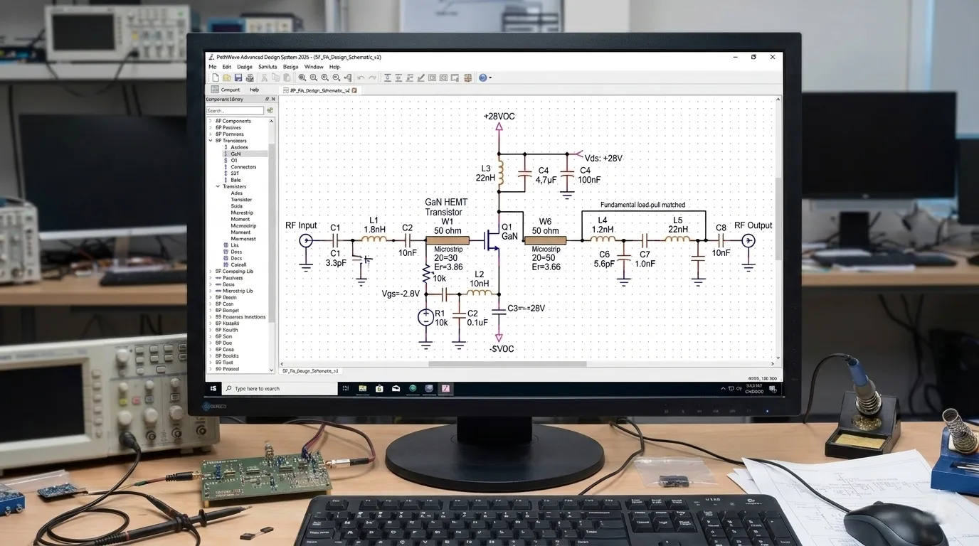
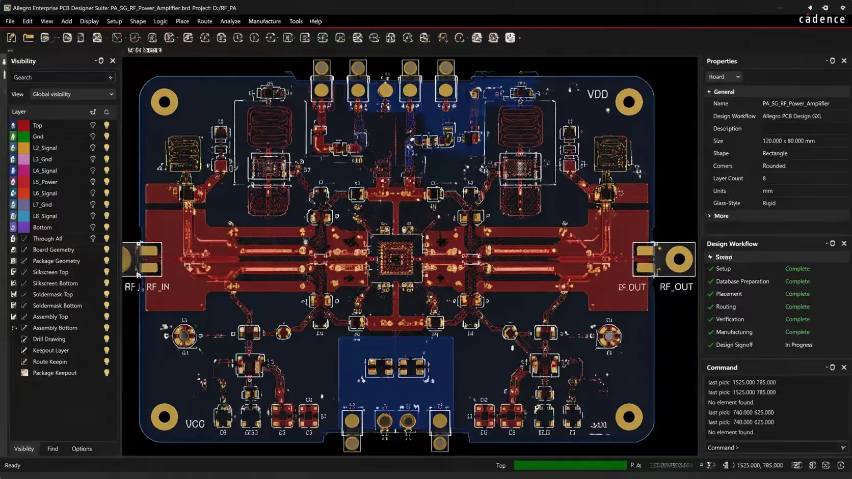
Simulation, using tools like load-pull in ADS, is where you validate your choices and fine-tune matching networks. The layout phase is just as critical. It's where you translate the ideal simulation into a real-world PCB, managing thermal paths and parasitic effects7.
Now, and only now, is it time to open your design software. With clear specs and a chosen technology and topology, your simulation work becomes focused and efficient. You are no longer guessing; you are verifying and optimizing a solid plan. The goal of simulation is to create the ideal matching networks to get the desired performance from your transistor. This involves running source-pull and load-pull simulations to find the optimal impedances for gain, power, and efficiency. You also have to run stability analysis to ensure the amplifier won't oscillate.
From Simulation to Physical Reality
The layout is where the simulated perfection meets the messy reality of the physical world. I remember an early project where a 100W amplifier simulation looked perfect, but the prototype only delivered 50W. The problem? A long, thin trace on the PCB added unexpected inductance, completely detuning the output match. It was a hard lesson in how critical layout is.
Thermal Management
High-power devices like GaN transistors generate a lot of heat in a very small area. Your layout must provide a low-resistance thermal path to pull that heat away. This involves using thermal vias directly under the transistor, selecting the right substrate material, and designing for an adequate heat sink. Without this, the transistor's temperature will skyrocket, reducing its performance and lifespan.
Controlling Parasitics
In RF design, everything is a component. A PCB trace has inductance, and a pad has capacitance. Your layout must minimize these unwanted "parasitic" elements. This means keeping matching networks physically close to the transistor, using wide, short traces for low-inductance paths, and ensuring a solid, continuous ground plane.
How Do You Properly Test and Validate Your RF Amplifier?
Your amplifier is built, but does it actually meet the customer's requirements? Shipping a product that fails in the customer's system can damage your reputation and your business.
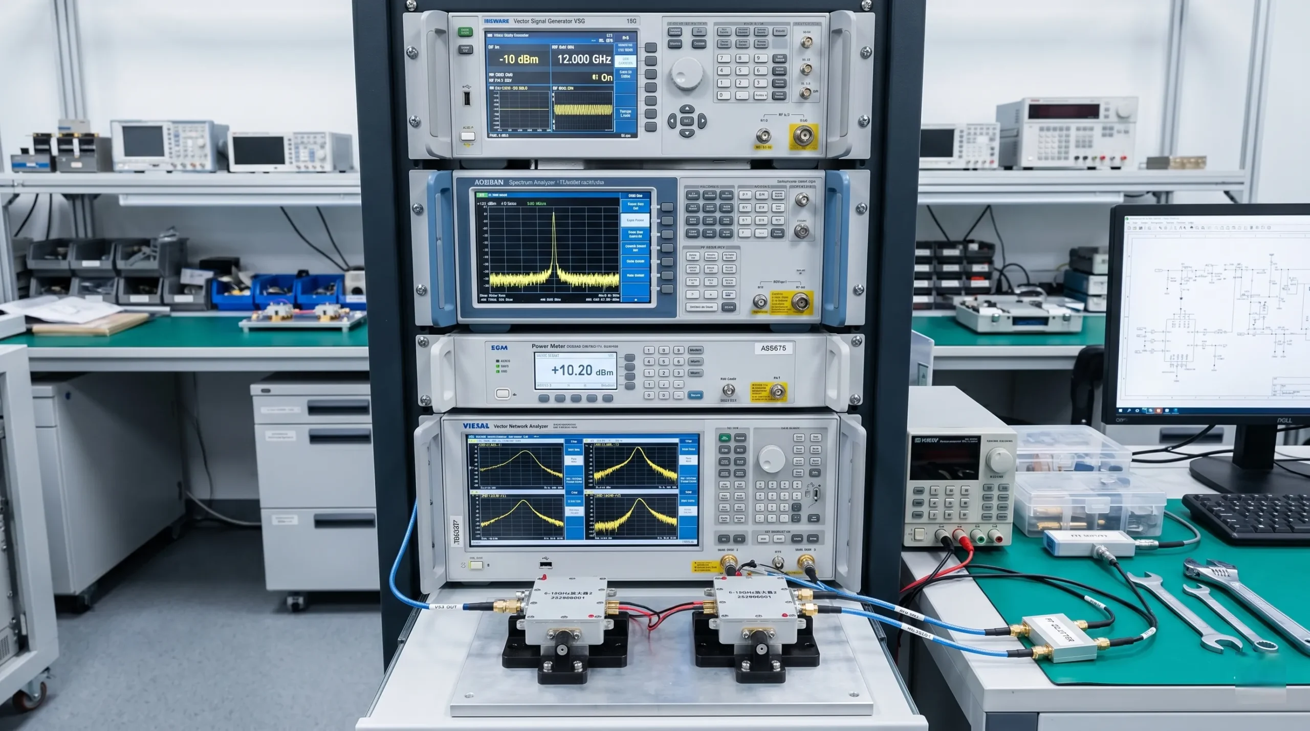
Testing involves a full suite of measurements using a Vector Network Analyzer (VNA), spectrum analyzer, and power meter. You must validate all key specs from step one, including linearity (ACLR/EVM) and stability, across the full specified temperature range.
The final step is to prove that the physical amplifier performs as designed. This is the moment of truth. At Safari Microwave, we believe in 100% testing for all our products because there is no substitute for real-world measurement. A comprehensive test plan should circle all the way back to the specifications you defined in the very first step.
The Key Stages of Testing
Testing is a multi-stage process, moving from basic checks to complex, system-level validation.
Small-Signal Testing
You start with a Vector Network Analyzer (VNA). This tool measures the S-parameters of your amplifier. S21 tells you the gain, while S11 and S22 tell you how good your input and output match are. You'll want to see flat gain and good matching across your entire frequency band.
Large-Signal Testing
Next, you apply real power. Using a signal generator, you drive the amplifier and measure its output power with a power meter. Here, you'll find the 1 dB compression point (P1dB) and saturated power (Psat). You also measure the gain and efficiency at these power levels.
Linearity Testing
For modern communication systems, this is crucial. You need to use a modulated signal, like a 5G or Wi-Fi signal, from a vector signal generator. A spectrum analyzer or vector signal analyzer is then used to measure adjacent channel leakage ratio (ACLR) and error vector magnitude (EVM). These measurements tell you how much distortion the amplifier adds, and they must meet the system's requirements.
Stress Testing
Finally, you have to ensure the amplifier is reliable. This involves testing it across its full specified operating temperature range, from cold to hot, to make sure performance is stable. You also test it at the limits of its supply voltage. This rigorous process is what gives us and our customers confidence in our products.
མཇུག་སྡོམ།
Building a great RF amplifier is a systematic process. It starts with deeply understanding the application, not with simulation software. This structured approach ensures performance, reliability, and saves you countless hours.
Find out which simulation tools can enhance your RF amplifier design process and improve accuracy. ↩
Discover the significance of error vector magnitude (EVM) in ensuring signal integrity. ↩
Learn about adjacent channel leakage ratio (ACLR) and its importance in RF amplifier performance. ↩
Explore methods for ensuring optimal impedance matching to enhance amplifier performance. ↩
Discover why linearity matters in RF amplifiers and how to achieve it in your designs. ↩
Explore the advantages of Doherty amplifiers for high-efficiency applications. ↩
Discover techniques to control parasitic elements that can degrade amplifier performance. ↩
