
Having trouble achieving wide frequency coverage with your RF amplifier1? The ongoing trade-offs among bandwidth, power, and efficiency can be frustrating. But with the right design strategies, this challenge can be solved.
To achieve ultra-broadband performance, focus on advanced matching network design2 using techniques like distributed amplifiers or negative feedback. Also, carefully select transistors with low parasitic capacitance. This combination minimizes impedance variation and maintains gain flatness3 across a wide frequency range.
I remember my boss once asking for a high-efficiency, top-linearity power amplifier. "No problem," I said, "give me three days." Then he added, "...and it needs to cover DC to 6 GHz." I told him I'd see him in thirteen days and to tell my family I love the Smith Chart4 if I didn't return. This joke highlights a serious truth: broadband design is incredibly complex. But if you break it down, the path becomes much clearer. Let's start with what I believe is half the battle.
Why are matching networks the biggest hurdle in broadband design?
Does your amplifier work perfectly at one frequency but fail across the band? This impedance mismatch kills your performance and power output. Let's look at how to create a proper wideband match.
Matching networks are difficult because a standard LC network is inherently narrow-band. For broadband, you need multi-section matching5, tapered transmission lines, or active matching techniques. These methods compensate for the transistor's changing impedance over frequency, ensuring stable power transfer.
Based on my 10 years of experience, if you get the matching network right, you're halfway to a successful design. The core problem is that everything changes with frequency, especially the impedance of your active device.
The Problem with Single-Frequency Matching
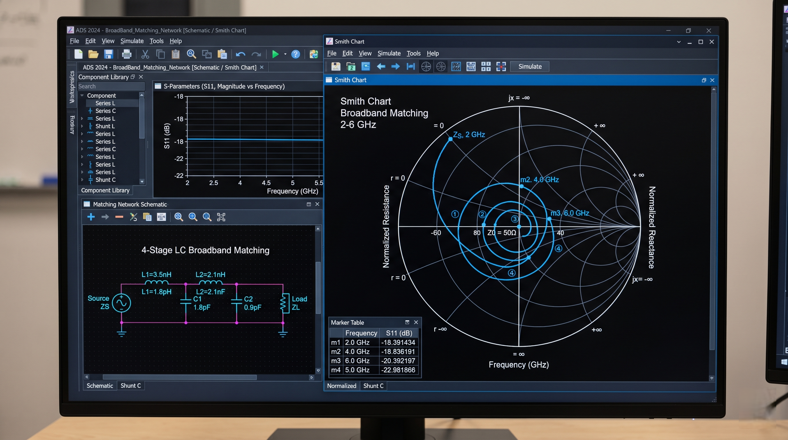
A simple LC matching network is designed to be resonant at one specific frequency. It perfectly transforms the device's impedance to the system impedance, usually 50 ohms, at that single point. But as you move away from that frequency, the match quickly falls apart. The component values are wrong for the new frequencies, causing reflections, power loss, and poor gain flatness3. This is why you need a strategy that works across the entire band, not just at one sweet spot. My best friend in these situations is the Smith Chart4, which helps me visualize how the impedance moves across the frequency range and plan my attack.
Multi-Stage and Tapered Solutions
For broadband success, you have to think differently. Instead of one perfect match, you create a series of "good enough" matches across the band. This is the idea behind multi-section matching5 networks. Each section handles a portion of the frequency range, and together they provide a decent match over a wide bandwidth. Another powerful technique is using tapered transmission lines6, where the impedance of the line gradually changes along its length. This provides a very smooth, wideband transition.
Here is a simple table to compare these approaches:
| Matching Technique | Best For | Complexity | Bandwidth |
|---|---|---|---|
| Lumped LC Network | Narrowband | Low | Narrow |
| Multi-Section LC | Moderate Bandwidth | Medium | Medium |
| Tapered Lines | Ultra-Broadband | High | Wide |
| Distributed Matching | Ultra-Broadband | High | Very Wide |
How do you balance bandwidth with power and efficiency?
Did you finally get the bandwidth you need, only to see efficiency plummet and your amplifier overheat? This trade-off feels impossible. But you can balance these competing goals with the right amplifier architecture.
Balancing these requires a strategic choice of amplifier class and topology. For example, a distributed amplifier offers exceptional bandwidth but often at lower efficiency. Techniques like the Doherty amplifier7 can improve efficiency, but they add complexity and may limit bandwidth.
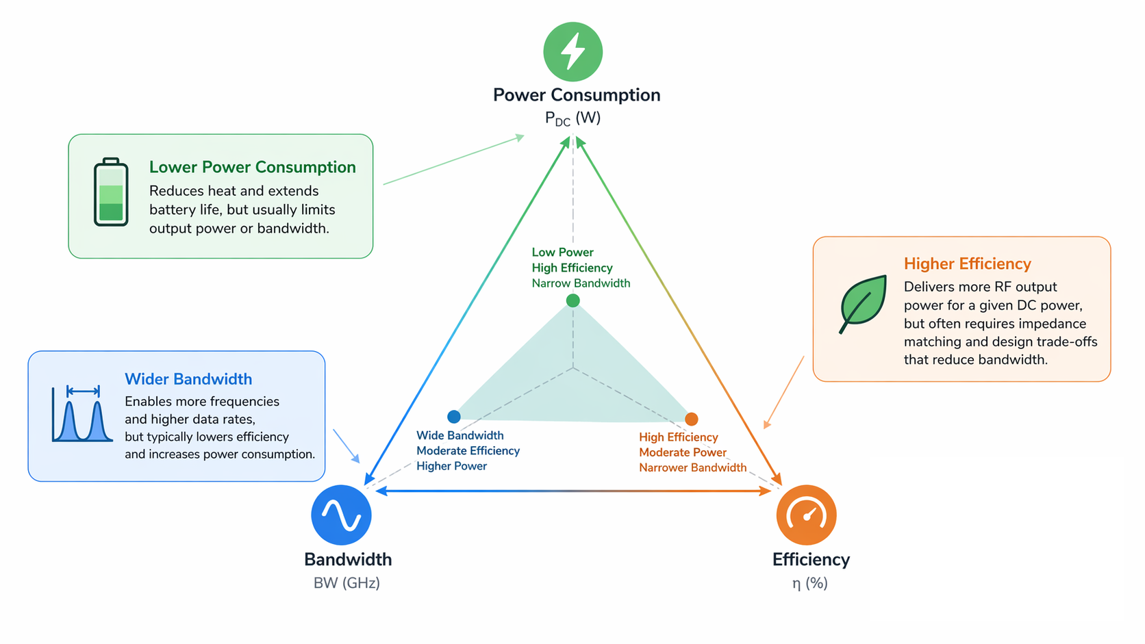
In RF amplifier1 design, I always think about the "iron triangle": bandwidth, power, and efficiency. You can pick two to be great, but it's nearly impossible to get all three. Pushing for more bandwidth almost always means you have to sacrifice some efficiency.
The Unbreakable Trade-Off
The components and matching techniques that work well over a wide frequency range are often lossier. Resistors used to flatten gain, for example, burn off power as heat. Also, the choice of amplifier class is critical. A Class A amplifier is very linear and behaves well over a wide bandwidth, but its theoretical maximum efficiency is only 50%, and in practice, it's often much lower. A high-efficiency mode like Class F can reach over 90% efficiency, but it relies on harmonic tuning, which is inherently a narrow-band technique. Trying to make a Class F amplifier work over a wide band is a major engineering challenge. This trade-off is fundamental to RF engineering.
Choosing the Right Amplifier Topology
The right architecture can help you find a better balance. For extreme bandwidth, the distributed amplifier is a classic solution. It uses a series of transistors where their parasitic capacitance8s are absorbed into artificial transmission lines. This allows for incredible bandwidths, which is how we achieve performance up to 110 GHz in our linear amplifiers. The downside is often lower power and efficiency. At Safari Microwave, our 30 years of engineering experience have been focused on solving these puzzles. Our 3000W saturated power amplifier, for instance, delivers both "High Power" and "Ultra-Wideband" performance by using advanced GaN devices9 and proprietary circuit topologies that push beyond these classic trade-offs.
What role does the transistor itself play in broadband amplification?
Your matching network is perfect, and you've chosen a topology, but the amplifier still falls short on bandwidth. The issue might be deeper. The transistor you choose is a critical foundation for any broadband design.
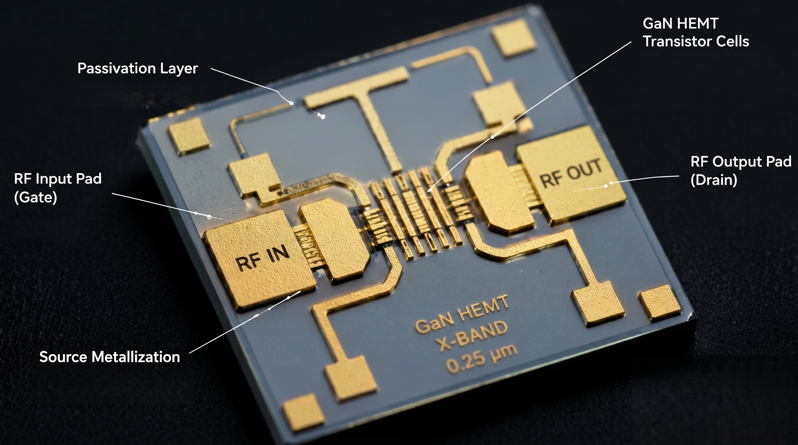
The transistor is crucial. Devices like GaN (Gallium Nitride) or GaAs (Gallium Arsenide) HEMTs offer high electron mobility and low parasitic capacitance8s. These intrinsic properties allow them to operate effectively over wider frequency ranges compared to older technologies like LDMOS.
You can have the best circuit design in the world, but you can't overcome the physical limitations of the active device. The transistor's own properties set the ultimate speed limit for your amplifier.
The Enemy Within: Parasitic Capacitance
Every transistor has internal, or "parasitic," capacitances. The most important ones are the gate-to-source capacitance (Cgs) and the gate-to-drain capacitance (Cgd). At low frequencies, these are not a big deal. But as frequency increases, their impedance drops. They start to act like tiny short circuits, shunting your precious RF signal away from where it needs to go. This effect is the primary reason why transistor gain naturally rolls off at high frequencies. To build a broadband amplifier, you must start with a transistor that has the lowest possible parasitic capacitance8s. This gives you a higher "speed limit" to begin with, making the job of the matching network much easier.
Why GaN and GaAs Win for Broadband
This is where modern semiconductor materials make all the difference. Technologies like Gallium Arsenide (GaAs) and Gallium Nitride (GaN) have fundamentally better physical properties for high-frequency operation compared to older silicon-based LDMOS. They have higher electron mobility, which allows for smaller transistors with lower parasitics. This is why for our ultra-wideband amplifiers and LNAs that reach 110 GHz, we use advanced GaAs and GaN devices9. They are the key to achieving "Ultra-Wideband" performance with "Low NF."
| Technology | Max Frequency | Power Density | Key Advantage for Broadband |
|---|---|---|---|
| LDMOS | < 4 GHz | High | Cost-effective for sub-4 GHz bands |
| GaAs | > 100 GHz | Medium | Excellent for high frequency, low noise |
| GaN | > 100 GHz | Very High | High power and high frequency combined |
GaN, in particular, also offers very high power density10. This means you can get more power out of a smaller device, which simplifies the matching challenge over a wide bandwidth.
Conclusion
Achieving ultra-broadband amplification comes down to mastering matching networks, choosing the right amplifier topology, and selecting the best transistor technology. Get these three things right, and you're on your way.
Explore comprehensive guides on RF amplifier design to enhance your understanding and skills. ↩
Learn about the critical role of matching network design in optimizing RF amplifier performance. ↩
Discover methods to ensure gain flatness across a wide frequency range in your RF amplifiers. ↩
Learn how to effectively use the Smith Chart for impedance matching and RF design. ↩
Explore the concept of multi-section matching and its benefits for broadband RF designs. ↩
Discover how tapered transmission lines can enhance performance in broadband RF applications. ↩
Learn about the benefits of using a Doherty amplifier for improved efficiency in RF designs. ↩
Understand the impact of parasitic capacitance on RF amplifier performance and design. ↩
Explore the benefits of using GaN devices for high-performance RF amplification. ↩
Discover the significance of high power density in RF devices for efficient design. ↩
